Analysis of the W-Cube 75 GHz beacon

W-Cube is a cubesat project from ESA with the goal of studying propagation in the W-band for satellite communications (71-76 GHz downlink, 81-86 GHz downlink). Current ITU propagation channel models for satellite communications only go as high as 30-40 GHz. W-Cube carries a 75 GHz CW beacon that is being used to make measurements to derive new propagation models. The prime contractor is Joanneum Research, in Graz (Austria). Currently, the 75 GHz beacon is active only when the satellite is above 10 degrees elevation in Graz.

Some months ago, a team from ESA led by Václav Valenta have started to make observations of this 75 GHz beacon using a portable groundstation in ESTEC (Neatherlands). The groundstation design is open source and the ESA team is quite open about this project. I have recently started to collaborate with them regarding opportunities to engage with the amateur radio community in this and future W-band propagation projects (there is an amateur radio 4 mm band, which usually covers from 75.5 to 81.5 GHz, depending on the country). As I write this, some of my friends in the Spain and Portugal microwave group are running tests with their equipment to try to receive the beacon.

On 2023-06-16, the team made an IQ recording of the beacon using their portable groundstation. They have published some plots about this observation. Now they have shared the recording with me so that I can analyse it. One of the things they are interested in is to evaluate the usage of the gr-satellites Doppler correction block to perform real-time Doppler correction with a TLE. So far they are doing Doppler correction in post-processing, but due to the high Doppler drift, it is not easy to see the uncorrected signal in a spectrum plot.

QO-100 orbit determination

In a previous post, I showed my experiment about measuring the phase difference of the 8APSK and BPSK beacons of the QO-100 NB transponder. The main goal of this experiment was to use this data to do orbit determination with GMAT. Over the last week I have continued these experiments and already have started to perform some orbit determination in GMAT.

Here I give an update about several aspects of the experiment, and show how I am setting up the orbit determination.

Calculating the QO-100 beacons frequency separation

In my previous post I set out to measure the phase difference between the QO-100 8APSK and BPSK beacons. One of the things I mentioned is that the frequency separation between these two beacons was approximately 1.6 Hz larger than the nominal 245 kHz.

A frequency error of a couple of Hz is typical when working with SDRs unless special care is taken. Many SDRs allow choosing the sample rate and centre frequency with great flexibility, but the drawback is that the frequencies that are achieved are often not exactly the ones we indicated. Fractional-N synthesis PLLs are used to generate the sampling clock and local oscillator, so there are small rounding errors in the generated frequencies.

With enough knowledge of how the SDR hardware works and how it is configured, it is possible to determine these frequency errors exactly, as a rational number \(p/q\) that we can calculate explicitly, multiplied by the reference frequency of the SDR. Then we can use this exact value to correct our measurements.

I have asked Mario Lorenz DL5MLO and Kurt Moraw DJ0ABR the details of how the beacons are generated in the Bochum groundstation. Two ADALM Pluto‘s are used: one generates the CW and BPSK beacons, and the other generates the 8APSK multimedia beacon. With the data they have given me, I have been able to compute the frequency separation of the 8APSK and BPSK beacons exactly, and the result matches well my experimental observations.

In this post we will look at how the fractional-N synthesis calculations for the Pluto can be done. Since the Pluto uses an AD9363 RFIC, these calculations are applicable to any product using one of the chips from the AD936x family, and to the FMCOMMS3 evaluation board.

Measuring the QO-100 beacons phase difference

Since a couple months ago, the QO-100 NB transponder has now two digital beacons being transmitted continuously: the “traditional” 400 baud BPSK beacon, and the new 2.4 kbaud 8APSK multimedia beacon. This transponder is an amateur radio bent-pipe linear transponder on board the Es’hail 2 GEO satellite. It has an uplink at 2400.25 MHz, a downlink at 10489.75 MHz, and 500 kHz bandwidth. The two beacons are transmitted from the AMSAT-DL groundstation in Bochum, Germany, with a nominal frequency separation of 245 kHz.

In some posts in the last few years (see this, for instance), I have been measuring the frequency of the BPSK beacon as received by my grounstation in Madrid, Spain. In these frequency measurements we can see the daily Doppler curve of the satellite, which is not completely stationary with respect to the surface of Earth. However, we can also see the frequency variations of the local oscillator of the transponder (including some weird effects called “the wiggles“). For this reason, the frequency of the BPSK beacon is not an ideal measurement for orbit determination, since it is contaminated by the onboard local oscillator.

If we measure the frequency (or phase) of the 8APSK and BPSK beacons and subtract the two measurements, the effects caused by the transponder local oscillator cancel out. The two beacons have slightly different Doppler, because they are not at the same frequency. The quantity that remains after the subtraction is only affected by the movement of the satellite.

Bochum and my station use both references locked to GPS. Therefore, the phase difference of the two beacons gives the group delay from Bochum through the transponder to my station. This indicates the propagation time of the signal, which is often known as three-way range. The three-way range is roughly the sum of distances between the satellite and each groundstation (roughly, but not exactly, due to the light-time delay). It is a quantity that is directly applicable in orbit determination.

In this post I present my first results measuring the phase difference of the beacons and the three-way range.

Timing SDR recordings with GPS

Following a discussion on Twitter about how to use satellite signals to check that distributed receivers are properly synchronized, I have decided to write a post about how to use GPS signals to timestamp an SDR recording. The idea is simple: we do a short IQ recording of GPS signals, and then process those signals to find the GPS time corresponding to the start of the recording. This can be applied in many contexts, such as:

  • Checking if the 1PPS synchronization in an SDR receiver is working correctly.
  • Timestamping an SDR recording without the need of a GPS receiver or 1PPS input, by first recording GPS signals for some seconds and then moving to the signals of interest (this only works if you’re able to change frequency without stopping the sample stream).
  • Measuring hardware delays between the 1PPS input and the ADC of an SDR (for this you need to know the hardware delay between the antenna connector and 1PPS output of your GPSDO).
  • Checking if synchronization is repetitive across restarts or power cycles.

We will do things in a fairly manual way, using a couple of open source tools and a Jupyter notebook. The procedure could certainly be automated more (but if you do so, at some point you might end up building a full fledged GPS receiver!). The post is written with a walk-through approach in mind, and besides the usefulness of timestamping recordings, it is also interesting to see hands-on how GPS works.

Waterfalls from the December 2021 eclipse frequency measurement

The HamSci Ham Radio Scienze Citizen Investigation community organized earlier this month the December 2021 Eclipse Festival of Frequency Measurement. The goal of this activity was to measure the frequency of HF time signals such as WWV and RWM over the course of ten days. The experiment lasted from December 1 to December 10, so it included the total eclipse over Antarctica of December 4, which happened between 5:29 and 9:37 UTC.

I participated in this activity with my HF station, which consists of a Hermes-Lite 2 beta2 DDC/DUC SDR transceiver and an end-fed random wire antenna about 17 metres long. I used a 10 MHz reference from a GPSDO as described in this post to lock the Hermes-Lite 2 sampling clock. Instead of measuring frequency in real time, I recorded IQ data at 200 sps for the WWV carrier at 5000, 10000 and 15000 kHz and for the RWM carrier at 4996, 9996 and 14996 kHz, so that the data could be post processed later with any kind of algorithms. I have published my recordings in the “December 2021 Eclipse Festival of Frequency Measurment IQ recording by station EA4GPZ” dataset in Zenodo.

In this post I process the IQ recordings to produce waterfalls that give us an overview of the data. The frequency measurement will be done in a later post.

Hermes-Lite 2 external 10 MHz reference

Interested by the forthcoming HamSci December 2021 eclipse festival of frequency measurement, I have decided to enable and test the external 10 MHz input of my Hermes-Lite 2 DDC/DUC HF transceiver. This will allow me to use a GPSDO (the Vectron MD-011 which has appeared in other posts) to reference the Hermes-Lite 2 in order to measure frequency accurately.

QO-100 spring eclipse season

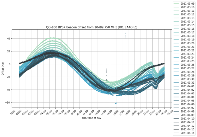
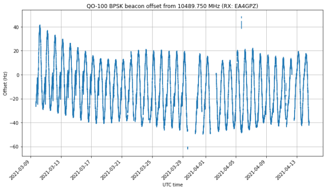
A few days ago, the spring eclipse season for Es’hail 2 finished. I’ve been recording the frequency of the NB transponder BPSK beacon almost 24/7 since March 9 for this eclipse season. In the frequency data, we can see that, as the spacecraft enters the Earth shadow, there is a drop in the local oscillator frequency of the transponder. This is caused by a temperature change in the on-board frequency reference. When the satellite exits the Earth shadow again, the local oscillator frequency comes back up again.

The measurement setup I’ve used for this is the same that I used to measure the local oscillator “wiggles” a year ago. It is noteworthy that these wiggles have completely disappeared at some point later in 2020 or in the beginning of 2021. I can’t tell exactly when, since I haven’t been monitoring the beacon frequency (but other people may have been and could know this).

A Costas loop is used to lock to the BPSK beacon frequency and output phase measurements at a rate of 100 Hz. These are later processed in a Jupyter notebook to obtain frequency measurements with an averaging time of 10 seconds. Some very simple flagging of bad data (caused by PLL unlocks) is done by dropping points for which the derivative exceeds a certain threshold. This simple technique still leaves a few bad points undetected, but the main goal of it is to improve the quality of the plots.

The figure below shows the full time series of frequency measurements. Here we can see the daily sinusoidal Doppler pattern, and long term effects both in the orbit and in the local oscillator frequency.

If we plot all the days on top of each other, we get the following. The effect of the eclipse can be clearly seen between 22:00 and 23:00 UTC.

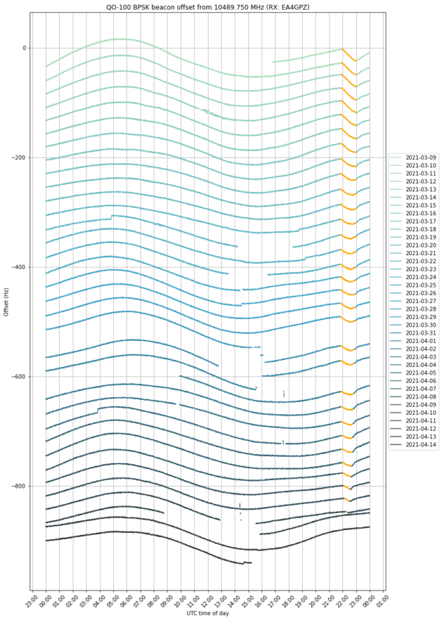
By adding an artificial vertical offset to each of the traces, we can prevent them from lying on top of each other. We have coloured in orange the measurements taken when the satellite was in eclipse. The eclipse can be seen getting shorter towards mid-April and eventually disappearing.

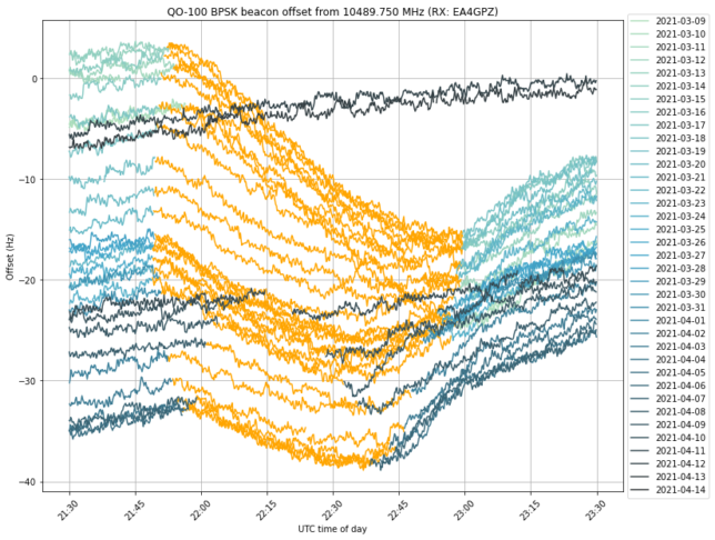
We see that the frequency drop starts exactly as soon as the eclipse starts. In many days, the drop ends at the same time as the eclipse, but in other days the drop ends earlier and we can see that the orange curve starts to increase again near the end of the eclipse. This can be seen better in the next figure, which shows a zoom to the time interval when the eclipse happens, and doesn’t apply a vertical offset to each trace. I don’t have an explanation for this increase in frequency before the end of the eclipse.

The plots in this post have been done in this Jupyter notebook. The frequency measurements have been stored in this netCDF4 file, which can be loaded with xarray.

Update on the QO-100 local oscillator wiggles

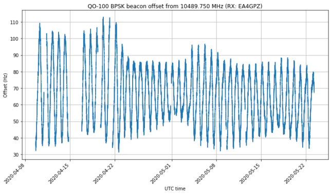
This post is a follow up to my study of the “wiggles” observed in the local oscillator of the QO-100 NB transponder. After writing that post, I have continued measuring the frequency of the BPSK beacon with my station almost without interruptions. Now I have some 44 days of measurements, spanning from April 9 to May 23. This data can be interesting to look at, so I’m doing this short post to share the data and look at it briefly.

The Jupyter notebook with all the data can be found here. The data is also linked in my jupyter_notebooks Github repository, which now uses git-annex to store the data in my home server. See the README for instructions on how to download some or all of the data files in the repository.

The whole time series can be seen in the figure below. We note that the typical Doppler sinusoidal curve varies slowly due to orbit perturbations and sometimes suddenly as a consequence of a station-keeping manoeuvre. I tweeted about one of the manoeuvres a while back.

There are now too many days in order to see things clearly when the frequency curves for each day are overlaid, but hopefully the figure below gives a good idea. We can see that the wiggles still happen approximately between 21:00 and 06:00 UTC, and between 11:00 and 17:00 UTC.

If we add an artificial offset of -15 Hz per day to the curves to prevent them from overlapping, we obtain the figure below. We see that the pattern of the wiggles keeps changing slightly, but also remains quite similar.

In my last post about this topic I said that it seemed that the wiggles repeated with a period of a sidereal day. Now it is clear that it is not the case. The wiggles seem to repeat roughly with a period of a solar day (24 hours). In fact, in 44 days sidereal time “advances” 2.88 hours with respect to solar time. However, it is clear that the wiggles haven’t shifted that much in time.

Wiggles in the QO-100 local oscillator

Some days ago, Hans Hartfuss DL2MDQ sent me an email about some frequency measurements of the QO-100 NB transponder BPSK beacon that he had been doing. The BPSK beacon is uplinked from Bochum (Germany) through the transponder, and as the beacon is generated using a very good Z3081A GPSDO as a reference, the frequency drift observed on the beacon downlink is caused by Doppler and the drift of the local oscillator of the transponder.

In his measurements, Hans observed some small oscillations or “wiggles” that didn’t seem to be caused by Doppler. Decided to investigate this, I started to do some measurements of my own. This post is an account of my measurements and findings so far.