The Arduino aquarium controller is an Arduino-compatible board designed to automate an aquarium. It can:
- Switch lightning on and off using a relay
- Control the temperature: it reads water temperature with a digital thermometer and uses a relay to switch a heater on and off
- Remember the user when it is time to feed
Specifications:
- DS3231M real time clock (with backup lithium battery).
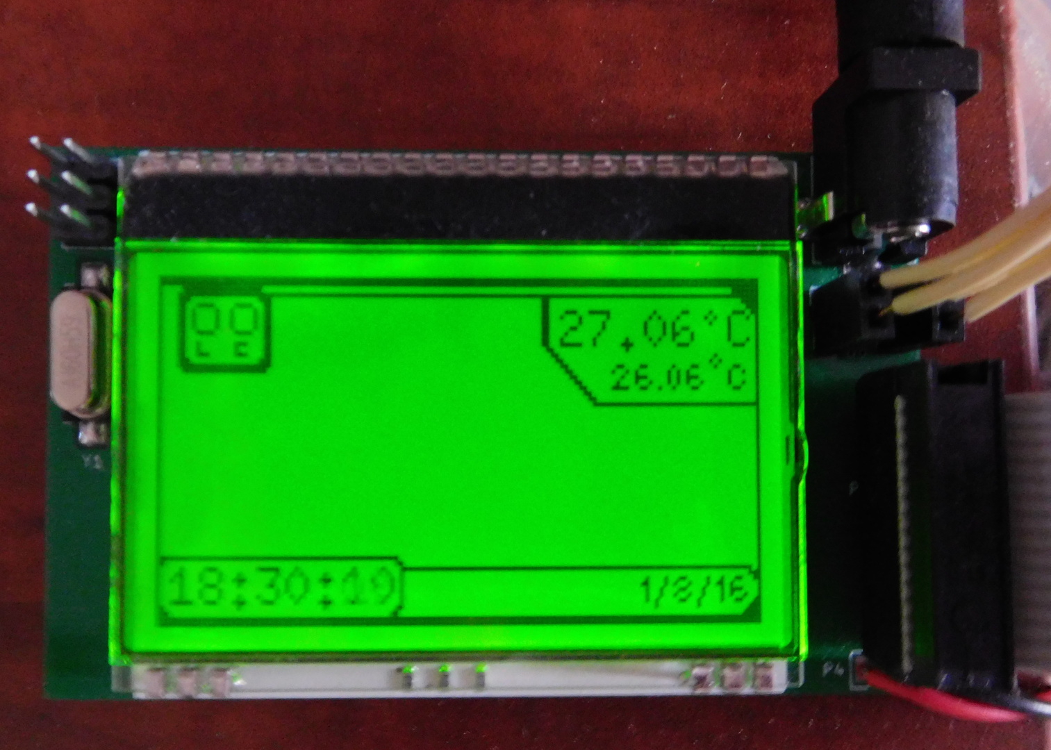
- DOGM128 LCD screen.
- 2x 12V relay drivers (to drive a lightning relay and a heater relay).
- 1-wire interface for a DS18S20 digital thermometer. The default software supports 2 thermometers, one for water temperature and the other for air temperature.
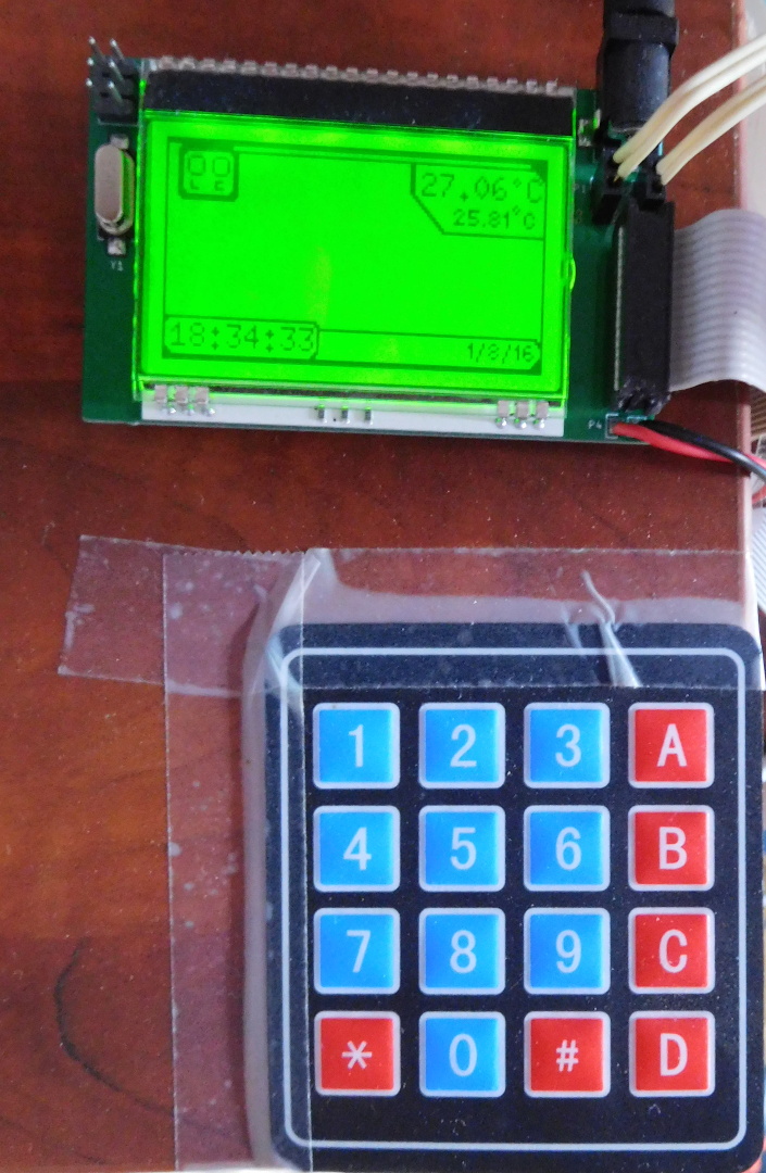
- Interface for a 4×4 matrix keyboard
- 12VDC input voltage (standard 2.1mm barrel jack). Power supply not included.
- Arduino-compatible ATmega328PB, programmable by ISP (no USB).
Related blog posts
Github project
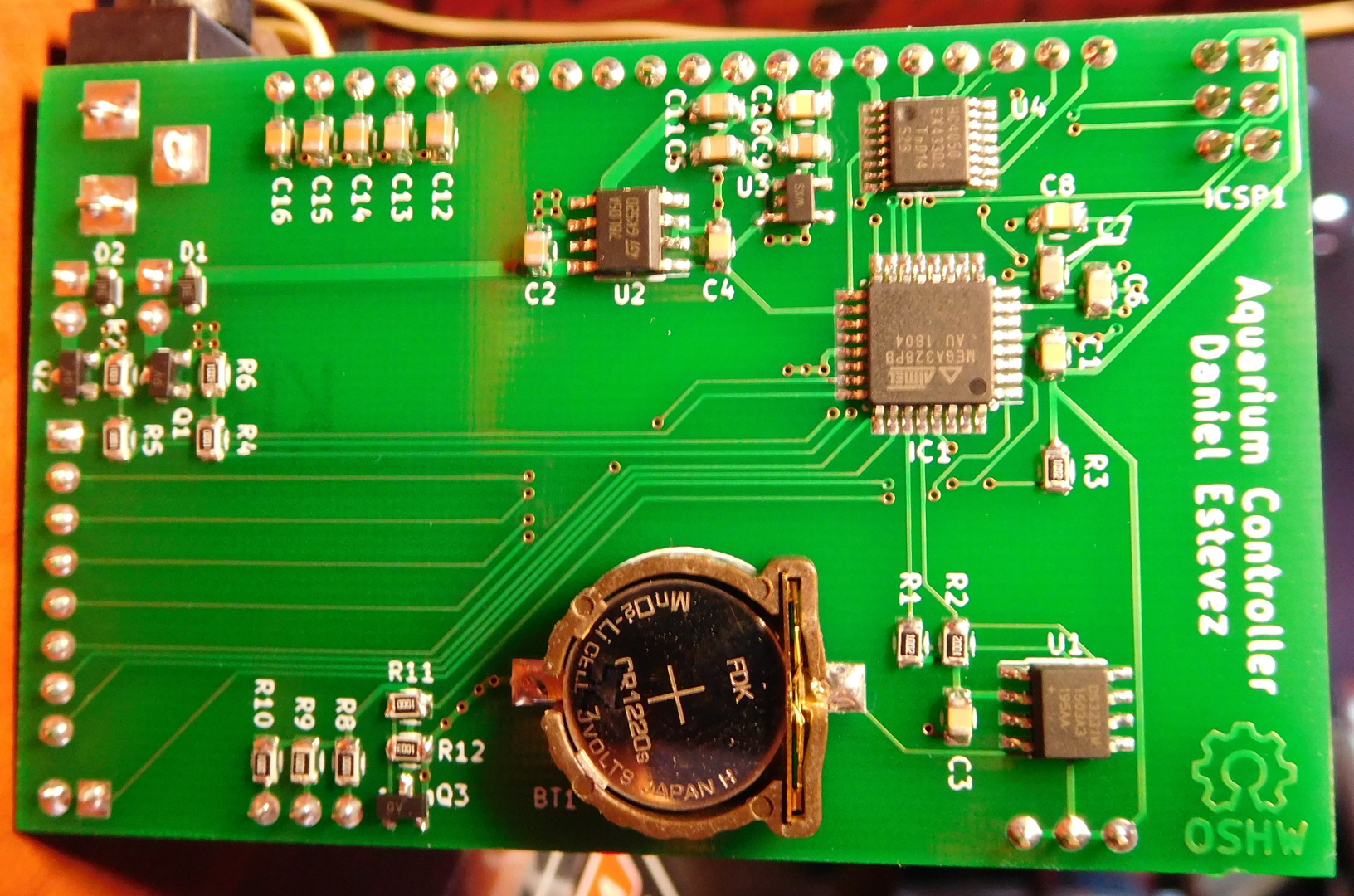
Note there is a small error in the current version of the PCBs. The enable pin of the 3.3V regulator is left floating. It should be connected to +5V. It is easy to fix this by scraping the coating of a nearby trace and making a solder bridge.
To build a complete aquarium controller, you will also need:
- One DS18S20 thermometer (two if you want to measure air temperature as well). You also need wire to connect the DS18S20 to the board. The board uses a female JST connector (another connector can be installed easily). Both DS18S20 can be connected to the same wire (in a bus manner). The DS18S20 that measures water temperature needs to be potted in a way that is impermeable and safe for the aquarium. I have mine inside a small plastic tube that is closed with hot glue and superglue (superglue is very impermeable and safe and prevents the hot glue from degrading inside the water).
- A 4×4 matrix keypad and a bus to connect it. The board has an 8×1 pin male header. My bus is scavenged from and old floppy or IDE bus.
- Two 12V relays and wire to connect them. You need one relay to control the lightning and another to control the heater. The board has 2×1 female headers, so you can just plug in the ends of the wire if you use solid core wire. The relays must be installed in a safe manner. One way to do this is to install them in the socket end of an AC extension chord and then close everything carefully with insulating tape.
- A 12V power supply. A 0.5A supply is enough. A lower current supply may be used, depending on the needs of the relays.