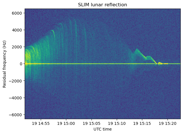
Lunar reflections during SLIM landing

In my previous post, I looked at the Doppler of the SLIM S-band telemetry signal during its landing on the Moon. I showed some waterfall plots of the signal around the residual carrier. In these, a reflection on the lunar surface was visible. The following figure shows a waterfall of the signal around the residual carrier, after performing Doppler correction and using a PLL to lock to the residual carrier. I was intrigued by the patterns made by these reflections, specially by some bands that look like a ‘1’ shape (the most prominent happens at 14:58).

In this post I study the geometry of the lunar reflection and find what causes these bands.

SLIM lunar landing radiometry

SLIM, JAXA’s Smart Lander for Investigating Moon, landed near Shioli crater on January 19. Shortly after the landing, the spacecraft was powered down to conserve power, since the probe had landed in an unexpected attitude which shaded its solar panels. After a few days of trying to contact SLIM, JAXA succeeded to reestablish communication with it on January 29. By then the Sun had moved west in the sky at SLIM’s location and had started illuminating the solar panels.

AMSAT-DL recorded the S-band signal from SLIM during the landing with the 20-meter antenna in Bochum Observatory. In this post I will analyse a recording done between 14:51:51 and 15:21:54 UTC (the touchdown was at 15:20 UTC). I will study the Doppler of the residual carrier and other radiometric quantities rather than the telemetry.

Receiving HADES-D

HADES-D is the 9th PocketQube developed by AMSAT-EA. It is the first one that hasn’t failed early in the mission. Among the previous AMSAT-EA satellites, GENESIS-L and -N suffered the launch failure of the Firefly-Alpha maiden flight, EASAT-2 and HADES presumably failed to deploy their antennas, GENESIS-G and -J flew on the second Firefly-Alpha flight, which only achieved a short-lived orbit, with all the satellites reentering in about a week, URESAT-1 had the same kind of antenna deployment problem, and GENESIS-A is a short duration payload scheduled to fly in the Ariane-6 maiden flight, which hasn’t happened yet.

HADES-D launched with the SpaceX Transporter 9 rideshare on November 11. This PocketQube was carried in the ION SCV-013 vehicle, and was released on November 28. The antennas have been deployed correctly, unlike in its predecessors, the satellite is in good health, and several amateur stations have been able to receive it successfully, so congratulations to AMSAT-EA.

Since HADES-D is the first PocketQube from AMSAT-EA that is working well, I was curious to measure the signal strength of this satellite. Back around 2016 I was quite involved in the early steps of AMSAT-EA towards their current line of satellites. We did some trade-offs between PocketQube and cubesat sizes and calculated power budgets and link budgets. Félix Páez EA4GQS and I wanted to build an FM repeater amateur satellite, because that suited best the kind of portable satellite operations with a handheld yagi that we used to do back then. Using a PocketQube for this always seemed a bit of a stretch, since the power available wasn’t ample. In fact, around the time that PocketQubes were starting to appear, some people were asking if this platform could ever be useful for any practical application.

Fast forward to the end of 2023 and we have HADES-D in orbit, with a functioning FM repeater. My main interest in this satellite is to gather more information about these questions. I should say that I was only really active in AMSAT-EA’s projects during 2016. Since then, I have lost most of my involvement, only receiving some occasional informal updates about their work.

Analysis of the W-Cube 75 GHz beacon

W-Cube is a cubesat project from ESA with the goal of studying propagation in the W-band for satellite communications (71-76 GHz downlink, 81-86 GHz downlink). Current ITU propagation channel models for satellite communications only go as high as 30-40 GHz. W-Cube carries a 75 GHz CW beacon that is being used to make measurements to derive new propagation models. The prime contractor is Joanneum Research, in Graz (Austria). Currently, the 75 GHz beacon is active only when the satellite is above 10 degrees elevation in Graz.

Some months ago, a team from ESA led by Václav Valenta have started to make observations of this 75 GHz beacon using a portable groundstation in ESTEC (Neatherlands). The groundstation design is open source and the ESA team is quite open about this project. I have recently started to collaborate with them regarding opportunities to engage with the amateur radio community in this and future W-band propagation projects (there is an amateur radio 4 mm band, which usually covers from 75.5 to 81.5 GHz, depending on the country). As I write this, some of my friends in the Spain and Portugal microwave group are running tests with their equipment to try to receive the beacon.

On 2023-06-16, the team made an IQ recording of the beacon using their portable groundstation. They have published some plots about this observation. Now they have shared the recording with me so that I can analyse it. One of the things they are interested in is to evaluate the usage of the gr-satellites Doppler correction block to perform real-time Doppler correction with a TLE. So far they are doing Doppler correction in post-processing, but due to the high Doppler drift, it is not easy to see the uncorrected signal in a spectrum plot.

Real time Doppler correction with GNU Radio

Satellite RF signals are shifted in frequency proportionally to the line-of-sight velocity between the satellite and groundstation, due to the Doppler effect. The Doppler frequency depends on time, on the location of the groundstation, and on the orbit of the satellite, as well as on the carrier frequency. In satellite communications, it is common to correct for the Doppler present in the downlink signals before processing them. It is also common to correct for the uplink Doppler before transmitting an uplink signal, so that the satellite receiver sees a constant frequency.

For Earth satellites, these kinds of corrections can be done in GNU Radio using the gr-gpredict-doppler out-of-tree module and Gpredict (see this old post). In this method, Gpredict calculates the current Doppler frequency and sends it to gr-gpredict-doppler, which updates a variable in the GNU Radio flowgraph that controls the Doppler correction (for instance by changing the frequency of a Frequency Xlating FIR Filter or Signal Source).

I’m more interested in non Earth orbiting satellites, for which Gpredict, which uses TLEs, doesn’t work. I want to perform Doppler correction using data from NASA HORIZONS or computed with GMAT. To do this, I have added a new Doppler Correction C++ block to gr-satellites. This block reads a text file that lists Doppler frequency versus time, and uses that to perform the Doppler correction. In this post, I describe how the block works.

GPS SVN49 broadcasting non-standard codes again

As a GNSS engineer at my day job in GMV, it’s not uncommon to find myself looking at spectrums of the GNSS signal bands, either on a spectrum analyzer or on an IQ recording done by an SDR. A few days ago, I spotted something in the L1 band (1575.42MHz) that quickly caught my eye: a pair of strong carriers at +/- 511.5kHz away from the L1 centre frequency. This was visible on some of the recordings that we had done in the last few days, and also live on a spectrum analyzer.

When monitoring the signal on the spectrum analyzer, it disappeared a few hours later, making me suspect that it was transmitted by a satellite rather than a local interferer. Back at home, I did some recordings with STRF to try to identify the satellite using its Doppler.

The Doppler signature of the signal was a perfect match for GPS SVN49, also as USA-203 and GPS IIRM-7. This satellite, launched in 2009, was the first to demonstrate the L5 signal. During in-orbit testing, an anomaly with its navigation signals caused by the L5 filter was discovered. The satellite was never put into operational use, and has been used for varied tests ever since.

After searching information about this satellite, I learned that some researchers from Torino, Italy, had already observed back in 2017 the same kind of signals that I was seeing.

This post is a detailed study of the L1 signal that is currently being broadcast by GPS SVN49. The data used here has been published in Zenodo as “RF recordings of GPS SVN49 broadcasting non-standard codes“.

Measuring QO-100 beacons frequency

Continuing with my frequency measurements of Es’hail 2, I have now been measuring the frequency of the beacons of the QO-100 narrowband transponder for several days. The main goal of these frequency measurements is to use Doppler to study the orbit of Es’hail 2. Previously, I had been doing frequency measurements on the engineering beacons at 10706MHz and 11205MHz. However, these beacons are currently being transmitted on a MENA beam, so I’m quite lucky to be in Spain, as they can’t be received in many other parts of Europe.

During the in-orbit tests of Es’hail 2, the engineering beacons were transmitted on a global beam, and I performed some differential Doppler studies with Jean Marc Momple 3B8DU, in Mauritius. The engineering beacons are no longer any good for these kind of studies, since their area of coverage is small. Thus, I have started to measure the beacons in the narrowband transponder, which covers all the satellite footprint.

Es’hail 2 frequency measurements

After being busy with other projects, I have resumed my frequency measurements of the Es’hail 2 beacons. The last measurement I performed was made when the satellite reached its operational slot at 26ºE. After manoeuvering to this spot, the Doppler was very small, on the order of 0.8ppb peak-to-peak, indicating a very accurate geostationary orbit. Now Es’hail 2 has been two months in its operational slot, inaugurating its Amateur transponders on February 14 and entering commercial service on March 7.

I am curious about studying again the Doppler at this point in the mission, to see how accurate the GEO orbit is. I am also interested in collaborating with other Amateurs to perform differential Doppler measurements, as I did with Jean Marc Momple 3B8DU. Here I detail the first results of my measurements.

Es’hail 2 stationed in 26ºE

If you’ve been following my posts about Es’hail 2, you’ll know that shortly after launch Es’hail 2 was stationed in a test slot at 24ºE. It remained in this slot until December 29, when it started to move to its operational slot at 26ºE. As of January 2, Es’hail is now stationed at 26ºE (25.8ºE, according to the TLEs).

The new GEO orbit at 26ºE is much more perfect than the orbit it had at 24ºE. This is to be expected for an operational orbit. Since December 30, I’ve been recording Doppler data of the satellite moving to its operational slot, and I have found some interesting effects of orbital dynamics in the data. This post is an account of these.

An STRF crash course

Recently, the STRF satellite tracking toolkit for radio observations by Cees Bassa has been gaining some popularity. This toolkit allows one to process RF recordings to extract frequency measurements and perform TLE matching and optimization via Doppler curves. Unfortunately, there is not a lot of documentation for this toolkit. There are some people that want to use STRF but don’t have a clear idea of where to start.

While I have tested very briefly STRF in the past, I had never used it for doing any serious task, so I’m also a newcomer. I have decided to test this tool and learn to use it properly, writing some sort of walk-through as I learn the main functionality. Perhaps this crash course will be useful to other people that want to get started with STRF.

As I have said, I’m no expert on STRF, so there might be some mistakes or omissions in this tutorial that hopefully the experts of STRF will point out. The crash course is organized as a series of exercises that explain basic concepts and the workflow of the tools. The exercises revolve around an IQ recording that I made of the QB50 release from ISS in May 2017. That recording is interesting because it is a wide band recording of the full 70cm Amateur satellite band on an ISS pass on May 29. During a few days before this, a large number of small satellites had been released from the ISS. Therefore, this recording is representative of the TLE lottery situation that occurs after large launches, where the different satellites haven’t drifted much yet and one is trying to match each satellite to a TLE.

The IQ recording can be downloaded here. I suggest that you download it and follow the exercises on your machine. After you finish all the exercises, you can invent your own. Certainly, there is a lot that can be tried with that recording.

A number of supporting files are created during the exercises. For reference, I have created a gist with these files.