Decoding LTE MIMO with a single antenna

In my previous post I decoded LTE PDSCH (physical downlink shared channel) transmissions from an IQ recording that I had made of an eNB recording using an USRP B205mini and a single antenna. The eNB has two antenna ports, and it uses TM4 (closed-loop spatial multiplexing) to transmit the PDSCH to each individual UE. In the post, I repeated several times that two-codeword TM4 is intended for 2×2 MIMO and relies on the receiver having at least 2 antennas in order to separate the two transmitted codewords, so I couldn’t decode these transmissions with my recording.

In this post I will show that in some cases this is not true, and these two-codeword TM4 transmissions can be decoded with just one receive antenna. I will decode some of these two-codeword transmissions from my IQ recording by using the ideas I introduce below.

LTE downlink: PDSCH

This post is a continuation of my series about LTE, where I decode a recording of the downlink signal of an eNB using Jupyter notebooks written from scratch. Here I will decode the PDSCH (physical downlink shared channel), which contains the data transmitted by the eNB to the UEs, including PDUs from the MAC layer, and some broadcast information, such as the SIB (system information block) and paging. At first I planned this post to be about decoding the SIB1. This is the first block of system information, and it is the next thing that a UE must decode after decoding the MIB (located in the PBCH) to find the configuration of the cell. The SIB1 is always transmitted periodically, and its contents and format are relatively well known a priori (as opposed to a user data transmission, which could happen at any time and contain almost anything), so it is a good example to try to decode PDSCH transmissions.

After writing and testing all the code to decode the SIB1, it was too tempting to decode everything else. Even though at first I wrote my code thinking only about the SIB1, with a few modifications I could decode all the PSDCH transmissions (except those using two-codeword spatial multiplexing, since my recording was done with a single antenna). I will still use the SIB1 as an example to show how to decode the PDSCH step by step, but I will also show the rest of the data.

The post is rather long, but we will get from IQ samples to looking at packets in Wireshark using only Python, so I think it’s worth its length.

A modern implementation of the Parks-McClellan FIR design algorithm

The Parks-McClellan FIR filter design algorithm is used to design optimal FIR filters according to a minimax criterion: it tries to find the FIR filter with a given number of coefficients whose frequency response minimizes the maximum weighted error with respect to a desired response over a finite set of closed sub-intervals of the frequency domain. It is based on the Remez exchange algorithm, which is an algorithm to find uniform approximations by polynomials using the equioscillation theorem. In signal processing, the Parks-McClellan algorithm is often call Remez. This algorithm is a very popular FIR design algorithm. Compared to the windowing method, which is another commonly used algorithm, it is able to obtain better filters (for instance, meeting design constraints with less coefficients), in part because it allows the designer to control the passband ripple and stopband attenuation independently by means of the weight function.

I have been laying some groundwork for Maia SDR, and for this I will need to run the Parks-McClellan algorithm in maia-httpd, the piece of software that runs in the Pluto ARM CPU. To evaluate what implementation of this algorithm to use, I have first gone to the implementations that I normally use: the SciPy remez function, and GNU Radio’s pm_remez function. I read these implementations, but I didn’t like them much.

The SciPy implementation is a direct C translation of the original Fortran implementation by McClellan, Parks and Rabiner from 1973. This C translation was probably written decades ago and never updated. The code is very hard to read. The GNU Radio implementation looks somewhat better. It is a C implementation that was extracted from Octave and dates from the 90s. The code is much easier to follow, but there are some comments saying “There appear to be some problems with the routine search. See comments therein [search for PAK:]. I haven’t looked closely at the rest of the code—it may also have some problems.” that have seemingly been left unattended.

Because of this and since I want to keep all the Maia SDR software under permissive open source licenses (the GNU Radio / Octave implementation is GPL), I decided to write from scratch an implementation of the Parks-McClellan algorithm in Rust. The result of this has been the pm-remez crate, which I have released recently. It uses modern coding style and is inspired by recent papers about how to improve the numerical robustness of the Parks-McClellan algorithm. Since I figured that this implementation would also be useful outside of Maia SDR, I have written Python bindings and published a pm-remez Python package. This has a few neat features that SciPy’s remez function doesn’t have. The Python documentation gives a walkthrough of these by showing how to design several types of filters that are commonly used. This documentation is the best place to see what pm-remez is capable of.

The rest of this post has some comments about the implementation and the things I’ve learned while working on this.

LTE Transmission Mode 4 (closed-loop spatial multiplexing)

This is a long overdue post. In 2022, I wrote a series of posts about LTE as I studied its physical layer to understand it better. In the last post, I decoded the PDCCH (physical downlink control channel), which contains control information about each PDSCH (physical downlink shared channel) transmission. I found that, in the recording that I was using, some PDSCH transmissions used Transmission Mode 4 (TM4), which stands for closed-loop spatial multiplexing. For an eNB with two antenna ports (which is what I recorded), this transmission mode sends either one or two codewords simultaneously over the two ports by using a precoding matrix that is chosen from a list that contains a few options. The choice is done by means of channel-state information from the UE (hence the “closed-loop” in the name).

In the post I found a transmission where only one codeword was transmitted. It used the precoding matrix \([1, i]^T/\sqrt{2}\). This basically means that a 90º phase offset is applied to the two antenna ports as they simultaneously transmit the same data. I mentioned that this was the reason why I obtained bad results when I tried to equalize this PDSCH transmission using transmit diversity in another previous post, and that in a future post I would show how to equalize this transmission correctly. I have realized that I never wrote this post, so now it is as good a time as any.

Demodulation of the 5G NR downlink

At the end of July, Benjamin Menkuec was commenting in Twitter about some issues he had while demodulating a 5G NR downlink recording. There was a lively discussion in which other people and I participated. I had never touched 5G, but had done some work with LTE, so I decided to take the chance to learn more about the 5G physical layer. Compared to LTE, the changes are more evolutionary than revolutionary, but understanding what has changed, and how and why, is part of the puzzle.

I had to take an 11.5 hour flight in a few days, so I thought it would be a nice challenge to give this a shot, take with me the recordings that Benjamin was using and all the 3GPP documents, and write a demodulator in a Jupyter notebook from scratch during the flight, as I had done in the past with my LTE recordings. This turned out to be an enjoyable and interesting experience, quite different from working at home in shorter intervals scattered over multiple days or weeks, and with internet access. At the end of the flight I had a mostly working demodulation, but it had a few weird problems that turned out to be caused by some mistakes and misconceptions. I worked on cleaning this up and solving the problems over the next few days, and also now preparing this post.

Rather than trying to give an account of all my mistakes and dead ends (I spoke a little about these in Twitter), in this post I will show the final clean solution. There are some tricky new aspects in 5G NR (phase compensation, as we will see below) which can be quite confusing, so hopefully this post will do a good job at explaining them in a simple way.

The Jupyter notebook used in this post is here, and the recording in SigMF format can be found in this folder. Here I will only be using the first of Benjamin’s two recordings, since they are quite similar. It was done with an ADALM Pluto at 7.86 Msps and has a duration of 143 ms. The transmitter is an srsRAN 5 MHz cell. The recording was done off-the-air, or maybe with a cabled set up, but there are some other signals leaking in. The SNR is very good, so this is not a problem.

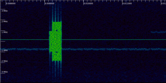
The first signal we find is at 9 ms. There is a transmission like this every 10 ms. As we will see, this is an SS/PBCH block. Something that stands out to those familiar with the LTE downlink spectrum is that the 5G NR spectrum is almost empty. In LTE, the cell-specific reference signals are transmitted all the time. In 5G this is not the case. Downlink signals are transmitted only when there is traffic. There is always a burst of one or several SS/PBCH blocks transmitted periodically (usually every 20 ms, but in this recording every 10 ms), as well as other signals that are always sent periodically (such as the SIB1 in the PDSCH), but this may be all if there is no traffic in the cell.

SS/PBCH block waterfall

Maia SDR

I’m happy to announce the release of Maia SDR, an open-source FPGA-based SDR project focusing on the ADALM Pluto. The first release provides a firmware image for the Pluto with the following functionality:

  • Web-based interface that can be accessed from a smartphone, PC or other device.
  • Real-time waterfall display supporting up to 61.44 Msps (limit given by the AD936x RFIC of the Pluto).
  • IQ recording in SigMF format, at up to 61.44 Msps and with a 400 MiB maximum data size (limit given by the Pluto RAM size). Recordings can be downloaded to a smartphone or other device.

A note about non-matched pulse filtering

This is a short note about the losses caused by non-matched pulse filtering in the demodulation of a PAM waveform. Recently I’ve needed to come back to these calculations several times, and I’ve found that even though the calculations are simple, sometimes I make silly mistakes on my first try. This post will serve me as a reference in the future to save some time. I have also been slightly surprised when I noticed that if we have two pulse shapes, let’s call them A and B, the losses of demodulating waveform A using pulse shape B are the same as the losses of demodulating waveform B using pulse shape A. I wanted to understand better why this happens.

Recall that if \(p(t)\) denotes the pulse shape of a PAM waveform and \(h(t)\) is a filter function, then in AWGN the SNR at the output of the demodulator is equal to the input SNR (with an appropriate normalization factor) times the factor\[\begin{equation}\tag{1}\frac{\left|\int_{-\infty}^{+\infty} p(t) \overline{h(t)}\, dt\right|^2}{\int_{-\infty}^{+\infty} |h(t)|^2\, dt}.\end{equation}\]This factor describes the losses caused by filtering. As a consequence of the Cauchy-Schwarz inequality, we see that the output SNR is maximized when a matched filter \(h = p\) is used.

To derive this expression, we assume that we receive the waveform\[y(t) = ap(t) + n(t)\]with \(a \in \mathbb{C}\) and \(n(t)\) a circularly symmetric stationary Gaussian process with covariance \(\mathbb{E}[n(t)\overline{n(s)}] = \delta(t-s)\). The demodulator output is\[T(y) = \int_{-\infty}^{+\infty} y(t) \overline{h(t)}\, dt.\]The output SNR is defined as \(|\mathbb{E}[T(y)]|^2/V(T(y))\). Since \(\mathbb{E}[n(t)] = 0\) due to the circular symmetry, we have\[\mathbb{E}[T(y)] = a\int_{-\infty}^{+\infty} p(t)\overline{h(t)}\,dt.\]Additionally,\[\begin{split}V(T(y)) &= \mathbb{E}[|T(y) – \mathbb{E}[T(y)]|^2] = \mathbb{E}\left[\left|\int_{-\infty}^{+\infty} n(t)\overline{h(t)}\,dt\right|^2\right] \\ &= \mathbb{E}\left[\int_{-\infty}^{+\infty}\int_{-\infty}^{+\infty} n(t)\overline{n(s)}\overline{h(t)}h(s)\,dtds\right] \\ &= \int_{-\infty}^{+\infty}\int_{-\infty}^{+\infty} \mathbb{E}\left[n(t)\overline{n(s)}\right]\overline{h(t)}h(s)\,dtds \\ &= \int_{-\infty}^{+\infty} |h(t)|^2\, dt. \end{split}\]Therefore, we see that the output SNR equals\[\frac{|a|^2\left|\int_{-\infty}^{+\infty} p(t) \overline{h(t)}\, dt\right|^2}{\int_{-\infty}^{+\infty} |h(t)|^2 dt.}.\]

The losses caused by using a non-matched filter \(h\), in comparison to using a matched filter, can be computed as the quotient of the quantity (1) divided by the same quantity where \(h\) is replaced by \(p\). This gives\[\frac{\frac{\left|\int_{-\infty}^{+\infty} p(t) \overline{h(t)}\, dt\right|^2}{\int_{-\infty}^{+\infty} |h(t)|^2\, dt}}{\frac{\left|\int_{-\infty}^{+\infty} |p(t)|^2\, dt\right|^2}{\int_{-\infty}^{+\infty} |p(t)|^2\, dt}}=\frac{\left|\int_{-\infty}^{+\infty} p(t) \overline{h(t)}\, dt\right|^2}{\int_{-\infty}^{+\infty} |p(t)|^2\, dt\cdot \int_{-\infty}^{+\infty} |h(t)|^2\, dt}.\]

We notice that this expression is symmetric in \(p\) and \(h\), in the sense that if we interchange \(p\) and \(h\) we obtain the same quantity. This shows that, as I mentioned above, the losses obtained when filtering waveform A with pulse B coincide with the losses obtained when filtering waveform B with pulse A. This is a clear consequence of these calculations, but I haven’t found a way to understand this more intuitively. We can say that the losses are equal to the cosine squared of the angle between the pulse shape vectors in \(L^2(\mathbb{R})\). This remark makes the symmetry clear, but I’m not sure if I’m satisfied by this as an intuitive explanation.

As an example, let us compute the losses caused by receiving a square pulse shape, defined by \(p(t) = 1\) for \(0 \leq t \leq \pi\) and \(p(t) = 0\) elsewhere, with a half-sine pulse shape filter, defined by \(h(t) = \sin t\) for \(0 \leq t \leq \pi\) and \(h(t) = 0\) elsewhere. This case shows up in many different situations. We can compute the losses as indicated above, obtaining\[\frac{\left(\int_0^\pi \sin t \, dt\right)^2}{\int_0^\pi \sin^2t\,dt\cdot \int_0^\pi dt} = \frac{2^2}{\frac{\pi}{2}\cdot\pi}= \frac{8}{\pi^2}\approx -0.91\,\mathrm{dB}.\]

GRCon22 Capture The Flag

I have spent a great week attending GRCon22 remotely. Besides trying to follow all the talks as usual, I have been participating in the Capture The Flag. I had sent a few challenges for the CTF, and I wanted to have some fun and see what challenges other people had sent. I ended up in 3rd position. In this post I’ll give a walkthrough of the challenges I submitted, and of my solution to some of the other challenges. The material I am presenting here is now in the grcon22-ctf Github repository.

Writing GUPPI files with GNU Radio and using SETI tools

GUPPI stands for Green Bank Ultimate Pulsar Processing Instrument. The GUPPI raw file format, which was originally used by this instrument for pulsar observations, is now used in many telescopes for radio astronomy and SETI. For instance Breakthrough Listen uses the GUPPI format as part of the processing pipeline, as described in this paper. The Breakthrough Listen blimpy tools work with GUPPI files or with filterbank files (basically, waterfalls) that have been produced from a GUPPI file using rawspec.

I think that GNU Radio can be a very useful tool for SETI and radio astronomy, as evidenced by the partnership of GNU Radio and SETI Institute. However, the set of tools used in the GNU Radio ecosystem (and by the wider SDR community) and the tools used traditionally by the SETI community are quite different, and even the file formats and some key concepts are unalike. Therefore, interfacing these tools is not trivial.

During this summer I have been teaching some GNU Radio lessons to the BSRC REU students. As part of these sessions, I made gr-guppi, a GNU Radio out-of-tree module that can write GUPPI files. I thought this could be potentially useful to the students, and it might be a first step in increasing the compatibility between GNU Radio and the SETI tools. (The materials for the sessions of this year are in this repository, and the materials for 2021 are here; these may be useful to someone even without the context of the workshop-like sessions for which they were created).

In this post I will show how gr-guppi works and what are the key concepts for GUPPI files, as these files store the output of a polyphase filterbank, which many people from the GNU Radio community might not be very familiar with. The goal of the post is to generate a simulated technosignature in GNU Radio (a CW carrier drifting in frequency) and then detect it using turboSETI, which is a tool for detecting narrowband signals with a Doppler drift.

Before going on, it is convenient to mention that an alternative to this approach is using gr-turboseti, which wraps up turboSETI as a GNU Radio block. This was Yiwei Chai‘s REU project at the ATA in 2021.

Real time Doppler correction with GNU Radio

Satellite RF signals are shifted in frequency proportionally to the line-of-sight velocity between the satellite and groundstation, due to the Doppler effect. The Doppler frequency depends on time, on the location of the groundstation, and on the orbit of the satellite, as well as on the carrier frequency. In satellite communications, it is common to correct for the Doppler present in the downlink signals before processing them. It is also common to correct for the uplink Doppler before transmitting an uplink signal, so that the satellite receiver sees a constant frequency.

For Earth satellites, these kinds of corrections can be done in GNU Radio using the gr-gpredict-doppler out-of-tree module and Gpredict (see this old post). In this method, Gpredict calculates the current Doppler frequency and sends it to gr-gpredict-doppler, which updates a variable in the GNU Radio flowgraph that controls the Doppler correction (for instance by changing the frequency of a Frequency Xlating FIR Filter or Signal Source).

I’m more interested in non Earth orbiting satellites, for which Gpredict, which uses TLEs, doesn’t work. I want to perform Doppler correction using data from NASA HORIZONS or computed with GMAT. To do this, I have added a new Doppler Correction C++ block to gr-satellites. This block reads a text file that lists Doppler frequency versus time, and uses that to perform the Doppler correction. In this post, I describe how the block works.