In February this year I was in the Spanish amateur microwave radio conference Micromeet 2025. In this conference, Luis Cupido CT1DMK presented a simple and inexpensive 10 GHz transverter that he called Nes-Transverter, with the motto “Instant microwaves. Just add solder”. The main idea of this design is that it is very simple and can be built by anyone with just a handful of inexpensive components. Luis was hoping that this project would help more people get on the 10 GHz band in a hands-on way, and he also wanted to demystify some ideas such as amateur microwave radio being difficult or expensive.
The schematic for this design is available here. It uses a 144 MHz IF, allowing it to be connected to a VHF amateur radio. An ADF4351 synthesizer, to be sourced from an inexpensive AliExpress dev board, generates a 2.556 GHz LO with complementary outputs. These two outputs are used in a frequency doubler built with two BAT15 diodes to produce a 5.112 GHz LO, which is filtered with a transmission line stub and amplified with an MMIC such as the ERA 3+. A harmonic x2 mixer built with two BAT15 diodes directly connected to the waveguide probe uses the 5.112 GHZ LO and the 144 MHz IF to produce 10.368 GHz, which is the usual frequency for terrestrial narrowband communications in the 10 GHz amateur band.
I was very interested by this talk, and thought that it would be fun to play with this project, since I haven’t done any hands-on electronics projects in quite a while. However, rather that building a transverter for narrowband communications, I decided to adapt the ideas to build a 10 GHz FMCW radar. I wanted to build a cheaper version of the ADALM-PHASER, minus the phased array part. The Phaser is an educational development kit from ADI that demonstrates concepts in phased array beamforming and FMCW radar. It uses an ADF4159 waveform generator synthesizer and a HMC735 VCO as a 12.2-12.7 GHz LO source that can be programmed to generate FMCW waveforms such as a linear sawtooth and triangle chirps. An ADALM-PLUTO or another SDR is used as a 2.2 GHz IF to obtain 10-10.5 GHz via high-side LO injection. On the transmit section, the 10-10.5 GHz signal is sent to an SMA connector to drive an external antenna. On the receive section, a 4×8 phased array of patches is included in the PCB. Each column of 4 patches is phased as a single element by connecting them together on the PCB. The 8 columns are beamformed in groups of 4 with two ADAR1000, which allows choosing independent complex coefficients for each column. Each of the 4-column beamformer outputs is connected to an RX channel of a 2-channel SDR, so that the final beamforming step can happen in software (see here for a block diagram of the Phaser).
The first thing I needed to replace in Luis design to convert it to an FMCW radar was the LO source. Since I will be using an SDR rather than a VHF radio as the IF, I could use an LO of around 4-4.5 GHz, which would give me around 10-10.5 GHz with an IF around 1-2 GHz. This meant that I could use the ADF4158 synthesizer as the LO source. This is the cheaper variant of the ADF4159, and it only goes up to 6.1 GHz instead of 13 GHz, which is fine for my use case. I needed a VCO to go together with the synthesizer, and after some looking around I decided to use another ADI part, the HMC319, which is a 3.9-4.45 GHz VCO. An IF of 1.6 GHz covers 10-10.5 GHz with an LO of 4.2-4.45 GHz, which is quite appropriate for this VCO choice.
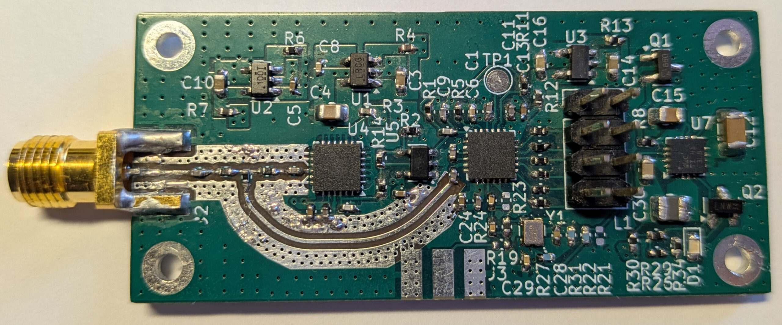
I designed a small PCB with an ADF4158 and HMC391, which I now have built and tested. In this post I explain some of the aspects of the board design and the results of the initial tests.
