Here I want to show a technique for measuring the gain of a dish that I first learned from an article by Christian Monstein about the Moon’s temperature at a wavelength of 2.77cm. The technique only uses power measurements from an observation of a radio source, at different angles from the boresight. Ideally, the radio source should be strong and point-like. It is also important that the angles at which the power measurements are made are known with good accuracy. This can be achieved either with a good rotator or by letting an astronomical object drift by on a dish that is left stationary.
Category: Hardware
Designing, building and testing amateur radio hardware.
Transmitting through QO-100 with the LimeNET Micro and LimeRFE
A couple weeks ago, I did a demo where I showed the LimeRFE radio frequency frontend being used as an HF power amplifier to transmit WSPR in the 10m band. Another demo I wanted to do was to show the LimeNET Micro and LimeRFE as a standalone 2.4GHz transmitter for the QO-100 Amateur radio geostationary satellite.
The LimeNET Micro can be best described as a LimeSDR plus Raspberry Pi, so it can be used as an autonomous transceiver or remotely through an Ethernet network. The LimeRFE has a power amplifier for 2.4GHz. According to the specs, it gives a power of 31dBm, or a bit over 1W. This should be enough to work QO-100 with a typical antenna.
You may have seen the field report article about the QO-100 groundstation I have in my garden. It is based around a LimeSDR Mini and BeagleBone Black single board ARM computer. The groundstation includes a driver amplifier that boosts the LimeSDR to 100mW, and a large power amplifier that gives up to 100W. The LimeSDR Mini and BeagleBone Black give a very similar functionality to the LimeNET Micro, but the LimeNET Micro CPU is more powerful.
The idea for this demo is to replace my QO-100 groundstation by the LimeNET Micro and LimeRFE, maintaining only the antenna, which is a 24dBi WiFi grid parabola, and show how this hardware can be used as a QO-100 groundstation.
WSPR with the LimeRFE
A few days ago, I received a LimeRFE from Andrew Back of Lime Microsystems. He was kind enough to send me a unit so that I can test it and make some usage demos during the ongoing crowdfunding campaign at Crowd Supply.
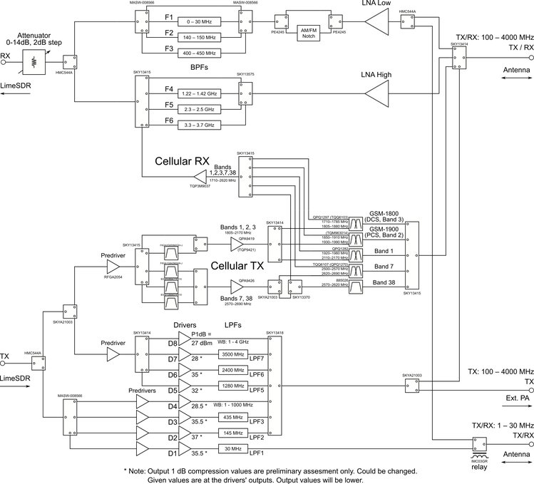
The LimeRFE is intended to work as an RF frontend for the LimeSDR family, although it can work coupled with any other SDR or conventional radio. As such, it has power amplifiers, filters and LNAs designed to cover the huge frequency range of these SDRs. It is designed to cover all the Amateur radio bands from HF up to 9cm, and a few cellular bands.
As anyone will know, designing broadband RF hardware is often quite difficult or expensive (Amateur radio amplifiers and LNAs are usually designed for a single band), so packing all this into a single unit is a considerable feat. The output power on most bands is around a couple watts, which is already enough for many experiments and applications. The block diagram of the LimeRFE can be seen below.
In this post I show a brief overview of the LimeRFE and demonstrate its HF transmission capabilities by showing a WSPR transmitter in the 10m band, using a LimeSDR as the transmitter.
NPR: Hamnet over 70cm
Some days ago, Guillaume F4HDK emailed me to introduce me his latest project, NPR (New Packet Radio). This is an open-source modem designed to carry IP traffic over the 70cm Amateur radio band, with data rates of up to 500kbps. The goal of this modem is to be used for the Hamnet Amateur radio IP network, to give access to end users where coverage on the 2.3GHz and 5GHz bands is poor due to the terrain.
Guillaume knew that I had worked on IP over 70cm with my CC1101 and Beaglebone black project, so he wanted to know what I though about NPR. After reading all the available documentation, I found NPR very interesting. Indeed, Guillaume has come up with clever ways of solving some of the difficulties I foresaw when planning out my experiments with the CC1101.
The most important aspect about NPR is that it is already a finished product that people can build as a kit and start using. My experiments with the CC1101 were a mixture of proof of concept and play around, and never progressed from that stage due to lack of interest in my local Amateur community. However, Guillaume has put a lot of time, thought and effort in developing NPR. Of course the project can evolve further, but it is usable in its present stage. In what follows, I do a detailed analysis of the technical aspects of NPR.
New dish for Es’hail 2 reception
I have replaced the dish I had for receiving Es’hail 2 by a new one. The former dish was a 95cm offset from diesl.es which was a few years old. I had previously used this dish for portable experiments, and it had been lying on an open balcony for many months until I finally installed it in my garden, so it wasn’t in very good shape.
Comparing with other stations in Spain, I received less transponder noise from the narrowband transponder of QO-100 than other stations. Doing some tests, I found out that the dish was off focus. I could get an improvement of 4dB or so by placing the LNB a bit farther from the dish. This was probably caused by a few hits that the dish got while using it portable. Rather than trying to fix this by modifying the arm (as the LNB couldn’t be held in this position), I decided to buy a new dish.
Recommendations for receiving Es’hail 2
A couple days ago, Janos Tolgyesi HG5APZ asked me by email about different hardware setups to receive the Amateur radio transponders on Es’hail 2, with an interest on inexpensive but effective solutions. He was quite happy with my detailed reply and convinced me to turn it into a blog post, so that other people can learn from it.
This post is intended for people that do not know much about Es’hail 2 but are interested in receiving it. If you’ve been investigating about the different setups that people are doing to receive it, then probably you’ll not learn anything new here. The post addresses questions such as “do I need a modified LNB” and similar.
Measuring the stability of a TCXO
Lately, I have been testing the GPSDO that I will use to discipline my Es’hail 2 groundstation. One of the tests I have done is to measure the frequency of the TCXO that I use in my Hermes-Lite 2.0beta2 over a few days. Here I show the details of the measurement process and how to process the data in Python.
Weird repair of the day: u-blox LEA-5S I2C interface
I have a DF9NP 10MHz GPSDO that is based on a u-blox LEA-5S GPS receiver. Essentially, the LEA-5S outputs an 800Hz signal that is used to discipline a 10MHz VCTCXO with a PLL. The LEA-5S doesn’t have persistent storage, so an I2C EEPROM is use to store the settings across reboots.
Lately it seemed that the reading of the settings from the EEPROM had failed. The u-blox was always booting with the default settings. This prevents the GPSDO from working, since the default for the timepulse signal is 1Hz instead of 800Hz. Here is the summary of my troubleshooting session and the weird repair that I did.
LimeSDR external reference quick HOWTO
To do accurate frequency measurements of Andrés EB4FJV‘s 2.3GHz beacon, I have needed to setup my LimeSDR to use my DF9NP 10MHz GPSDO as an external reference. This is a quick HOWTO with the steps to make the LimeSDR use an external reference.
Flashing a Vaisala RS41 radiosonde
The Vaisala RS41 radiosonde is a weather radiosonde that is currently being launched in Madrid Barajas and other sounding sites in Spain, Europe and Australia. I have already spoken about how to decode it. One of the most interesting aspects of this model is that the RS41 contains a STM32F1 ARM Cortex-M3 microcontroller, a SiLabs FSK transmitter, and a uBlox GPS receiver, whereas the older RS92 contained custom ASICs to perform these functions. Thus, it is easy to reflash this radiosonde and write custom firmware for it, giving a lot of possibilities for experimentation.
In STARcon 2018, Julián Santamaría from AEMET (the Spanish meteorological office) gave me an RS41. While I have some long-term ideas about how to use it as a propagation sounder, I have just started playing with it. In this brief note, I explain how to flash the radiosonde with custom firmware.