Since watching Matt Venn‘s video about flip-flop timing, I have had at the back of my mind the idea of designing my own ASIC flip-flop and doing some simulations to measure its timing parameters. This is partly an excuse to learn how to use Magic and other VLSI design tools, and partly a good way to understand better how the numbers that appear on a flip-flop datasheet relate to what physically happens in the flip-flop.
I have now designed a flip-flop in Magic and done ngspice simulations to measure its setup, hold and output delay times. This work can be found in a flip-flop-timing repository in Github. In this post I explain how the flip-flop is designed and how the timing analysis is done.
In February this year I was in the Spanish amateur microwave radio conference Micromeet 2025. In this conference, Luis Cupido CT1DMK presented a simple and inexpensive 10 GHz transverter that he called Nes-Transverter, with the motto “Instant microwaves. Just add solder”. The main idea of this design is that it is very simple and can be built by anyone with just a handful of inexpensive components. Luis was hoping that this project would help more people get on the 10 GHz band in a hands-on way, and he also wanted to demystify some ideas such as amateur microwave radio being difficult or expensive.
The schematic for this design is available here. It uses a 144 MHz IF, allowing it to be connected to a VHF amateur radio. An ADF4351 synthesizer, to be sourced from an inexpensive AliExpress dev board, generates a 2.556 GHz LO with complementary outputs. These two outputs are used in a frequency doubler built with two BAT15 diodes to produce a 5.112 GHz LO, which is filtered with a transmission line stub and amplified with an MMIC such as the ERA 3+. A harmonic x2 mixer built with two BAT15 diodes directly connected to the waveguide probe uses the 5.112 GHZ LO and the 144 MHz IF to produce 10.368 GHz, which is the usual frequency for terrestrial narrowband communications in the 10 GHz amateur band.
I was very interested by this talk, and thought that it would be fun to play with this project, since I haven’t done any hands-on electronics projects in quite a while. However, rather that building a transverter for narrowband communications, I decided to adapt the ideas to build a 10 GHz FMCW radar. I wanted to build a cheaper version of the ADALM-PHASER, minus the phased array part. The Phaser is an educational development kit from ADI that demonstrates concepts in phased array beamforming and FMCW radar. It uses an ADF4159 waveform generator synthesizer and a HMC735 VCO as a 12.2-12.7 GHz LO source that can be programmed to generate FMCW waveforms such as a linear sawtooth and triangle chirps. An ADALM-PLUTO or another SDR is used as a 2.2 GHz IF to obtain 10-10.5 GHz via high-side LO injection. On the transmit section, the 10-10.5 GHz signal is sent to an SMA connector to drive an external antenna. On the receive section, a 4×8 phased array of patches is included in the PCB. Each column of 4 patches is phased as a single element by connecting them together on the PCB. The 8 columns are beamformed in groups of 4 with two ADAR1000, which allows choosing independent complex coefficients for each column. Each of the 4-column beamformer outputs is connected to an RX channel of a 2-channel SDR, so that the final beamforming step can happen in software (see here for a block diagram of the Phaser).
The first thing I needed to replace in Luis design to convert it to an FMCW radar was the LO source. Since I will be using an SDR rather than a VHF radio as the IF, I could use an LO of around 4-4.5 GHz, which would give me around 10-10.5 GHz with an IF around 1-2 GHz. This meant that I could use the ADF4158 synthesizer as the LO source. This is the cheaper variant of the ADF4159, and it only goes up to 6.1 GHz instead of 13 GHz, which is fine for my use case. I needed a VCO to go together with the synthesizer, and after some looking around I decided to use another ADI part, the HMC319, which is a 3.9-4.45 GHz VCO. An IF of 1.6 GHz covers 10-10.5 GHz with an LO of 4.2-4.45 GHz, which is quite appropriate for this VCO choice.
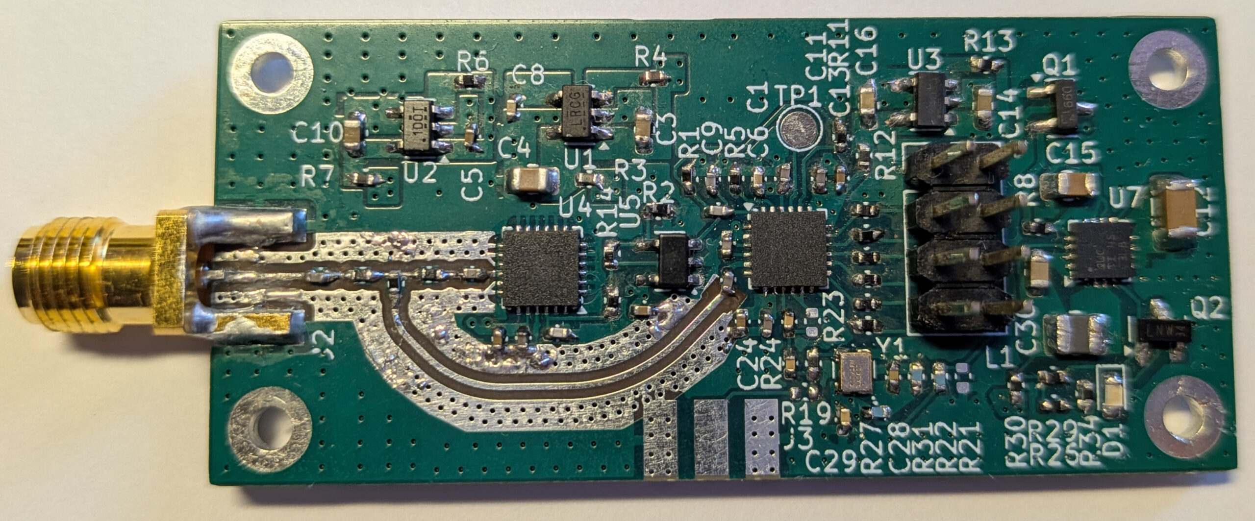
I designed a small PCB with an ADF4158 and HMC391, which I now have built and tested. In this post I explain some of the aspects of the board design and the results of the initial tests.
I have a DF9NP 10MHz GPSDO that is based on a u-blox LEA-5S GPS receiver. Essentially, the LEA-5S outputs an 800Hz signal that is used to discipline a 10MHz VCTCXO with a PLL. The LEA-5S doesn’t have persistent storage, so an I2C EEPROM is use to store the settings across reboots.
Lately it seemed that the reading of the settings from the EEPROM had failed. The u-blox was always booting with the default settings. This prevents the GPSDO from working, since the default for the timepulse signal is 1Hz instead of 800Hz. Here is the summary of my troubleshooting session and the weird repair that I did.
I have made a mains choke for my HF station, following Ian GM3SEK’s design, which involves twisting the three mains wires together and passing as many turns as possible through a Fair-Rite 0431177081 snap-on ferrite core. I wanted to measure the choke’s impedance to get an idea of its performance, so I’ve used my Hermes-Lite 2.0 beta2 in VNA mode.
In a previous post, I talked about the possibility of changing the transmit frequency of a Vaisala RS92-SGP radiosonde by modifying the settings on its EEPROM. The lowest frequency you can achieve using this method is 400MHz and the highest probably depends on the particular unit, but it is somewhat between 410MHz and 423MHz. There are also reports of very low output power on the highest frequencies (I’ll explain why below). Clearly, this can’t be used to make the radiosonde transmit in 430MHz, inside the 70cm Amateur band. In fact, from what I’ve read online, the impression is that it’s not possible to modify the radiosonde to make it transmit in 430MHz. However, I wanted to try to feed an external reference to see what happened. Short story: it doesn’t work either. However, I discovered some interesting information about the RF section of the RS92-SGP along the way.
I’ve started to experiment with the RS92-SGP radiosonde that I recovered some days ago. The radiosonde has a M95256-W 32KB SPI EEPROM where all the code and settings are stored, since the onboard CPU/DSP doesn’t have any flash memory. Several parts of the firmware, including some of the settings have being reverse engineered. Thus, it is useful to interface the EEPROM to a microcontroller to rewrite some settings, perhaps to change the transmit frequency or the radiosonde’s ID (the serial number which is also printed on the radisonde’s box).
I wanted to build something easy and useful this summer, so I have gone with a 12V (also adjustable to 13.8V) 5A linear power supply. The design is based on the 12V 15A power supply by Ed WA1TWX that appears in the 2015 ARRL Handbook. The main difference is that I’m using only one pass transistor instead of three. Here I describe my design.
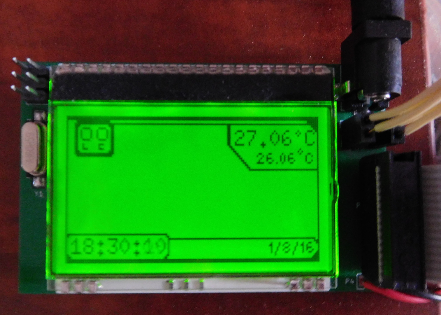
Just a quick note that I’ve finally put the page for my Arduino aquarium controller. This is a project that I built several years ago to control a small aquarium at home. I built it with through-hole parts on a home etched single-side PCB. Now I’ve redesigned the project to use SMD parts and double-sided PCB.
This is a follow up to a previous post where I investigated the phase noise of 27MHz references to be used for a 10GHz receiver. Dieter DF9NP has being kind enough to send me a 10MHz 0.25ppm TCXO to do some more tests.
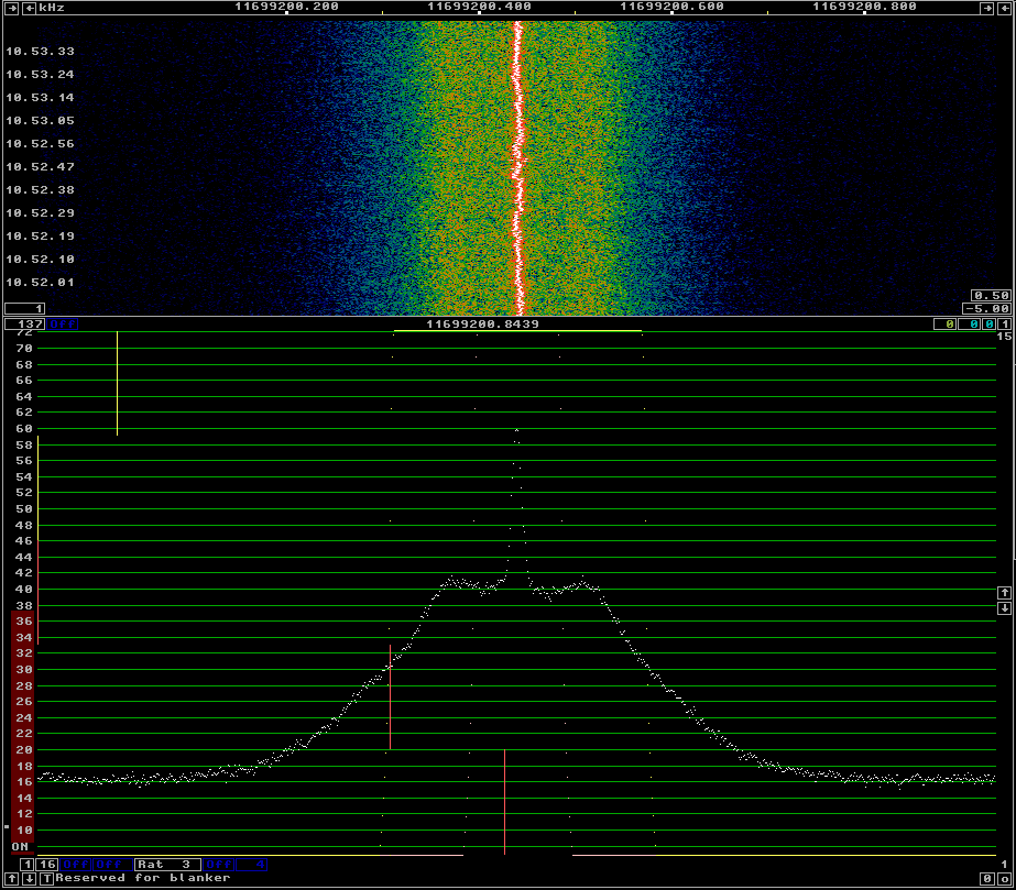
I’ve connected the 10MHz TCXO to the DF9NP 27MHz PLL and used it to receive the beacon of BADR-5, as I did in the previous post. The phase noise of the 10MHz TCXO + 27MHz PLL can be seen in the following figure.
10MHz 0.25ppm TCXO and 27MHz PLL
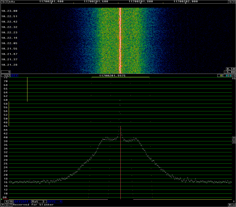
For comparison, see below the phase noise with the DF9NP 10MHz GPSDO and 27MHz PLL. There is not much difference between both. This seems to indicate that the culprit of the phase noise is the 27MHz PLL, as the 10MHz TCXO should be quite clean.
Today, I’ve being measuring the phase noise of the different 27MHz references that I have for my Ku-band LNBF. The LNBF is an Avenger PLL321S-2. I’ve modified it, removing the 27MHz crystal and including a connector for an external 27MHz reference signal. In my lab, I have the following equipment to generate a 27MHz signal:
OCXO/Si5351A kit. This kit includes a 27MHz OCXO and a Si5351A frequency synthesizer. The Si5351A can act as a buffer and output the OCXO signal directly or generate a 27MHz clock.
A DF9NP 27MHz PLL and a DF9NP GPSDO. The GPSDO generates a 10MHz signal which is locked to GPS. The PLL generates a 27MHz from the 10MHz signal.
I’ve used linrad to receive the beacon of BADR-5 at 11966.2MHz using different references for the 27MHz signal. The AFC in linrad tries to compensate for any drift in the reference or the satellite beacon. By averaging, one can get good plots of the sideband noise of the beacon. This is far from a proper lab test, but it gives a good idea of the performance of the references.