A few days ago I tried to measure the QO-100 NB transponder LO stability using my DF9NP 10MHz GPSDO. It turned out that my GPSDO was less stable than the LO, so my measurements showed nothing about the QO-100 LO. Carlos Cabezas EB4FBZ has been kind enough to lend me a Vectron MD-011 GPSDO, which is much better than my DF9NP GPSDO and should allow me to measure the QO-100 LO.
Before starting the measurements with QO-100, I have taken the time to use the Vectron GPSDO to measure the Allan deviation of my DF9NP GPSDO over several days. This post is an account of the methods and results.
Lately, I have been testing the GPSDO that I will use to discipline my Es’hail 2 groundstation. One of the tests I have done is to measure the frequency of the TCXO that I use in my Hermes-Lite 2.0beta2 over a few days. Here I show the details of the measurement process and how to process the data in Python.
Last week I did an experiment where I transmitted WSPR on a fixed frequency for several days and studied the distribution of the frequency reports I got in the WSPR Database. This can be used to study the frequency accuracy of the reporters’ receivers.
I was surprised to find that the distribution of reports was skewed. It was more likely for the reference of a reporter to be low in frequency than to be high in frequency. The experiment was done in the 40m band. Now I have repeated the same experiment in the 20m band, obtaining similar results.
Over the last few days I’ve been transmitting WSPR on 40m with 20dBm of power using my Hermes-Lite 2.0beta2. For this, I’m using the instrument output of the Hermes-Lite, which is driven by an OPA2677 200MHz dual opamp that produces a maximum output of 20dBm. I’ve been transmitting always on the frequency 7040100Hz. I have been collecting the reports from the WSPR database for a total of 2518 reports over 5 days of activity.
There are many statistics that can be done with this data, but since I have always been transmitting on the same frequency, it is quite interesting to look at the frequency in the reports. My Hermes-Lite is quite stable in frequency, as it uses a 0.5ppm 38.4MHz TCXO from Abracon. In fact, in the shack its stability is usually much better than 0.5ppm. During these tests I have verified the accuracy of the Hermes-Lite frequency by receiving my DF9NP 27MHz PLL, which is driven with a DF9NP 10MHz GPSDO. The 27MHz signal is usually reported around 3Hz high by the Hermes-Lite, with a drift of roughly 0.3Hz. This accounts for an error of 0.1ppm, and the drift is around 10ppb.
It seems that this performance is much better than the usual performance of the Amateur radio transceivers that report on the WSPR network, so the frequency reports can be used to measure the error of the frequency references in these Amateur radio transceivers. Noting that at 27MHz my Hermes-Lite is 3Hz low in frequency, I have determined a correction of -0.782Hz for my WSPR frequency, so I have chosen to take my transmission frequency as 7040099.218Hz when doing the calculations. This is probably accurate to a few tens of ppb.
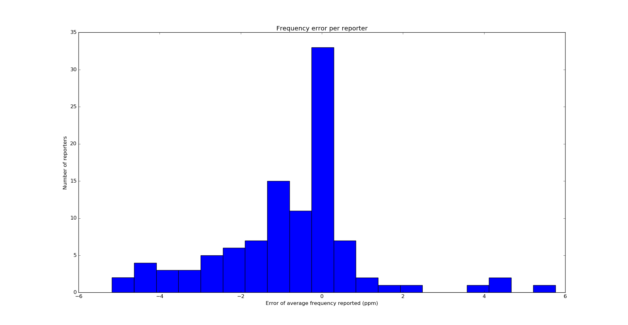
I wanted to do a statistic of the distribution of the error in the frequency references of the WSPR receivers. To do this, I’ve decided that it’s better to first do, for each reporter, an average of the frequency of its reports, and then take this average as the frequency measured by that reporter. Then I do a histogram of the errors in the frequency reported by each reporter. The first average is done because there are some reporters which have a great number of reports with a very similar frequency (because their receiver might have an error, but it doesn’t drift much), and so the histogram would be biased with these reports if I just plotted the histogram of all the frequency reports. The histogram is shown below.
Frequency error of WSPR reporters
I find this histogram rather surprising. I expected to get a normal distribution or something similar, or at least a symmetric histogram centred on an error of 0ppm. However, the histogram is clearly skewed to the left. We conclude from this that a good number of WSPR receivers are quite accurate in frequency, and have an error of 0.5ppm or less. However, from those that are not accurate, it is much more probable that they are low in frequency (so they report me at a higher frequency).
I still have to find a good explanation for this effect. However, I have suspicions that this has something to do with the way that the frequency of a quartz crystal depends on the temperature (and this depends on the way that the crystal is cut). I have found in this document the image below.
Note that non-AT-cut crystals are low in frequency over most of the temperature range, so I can’t help but think that this is too much of a coincidence with the skew in my histogram above. Other people have pointed out that this is not so simple, as for instance the adjustment of the tuning capacitors of the crystal oscillator also plays an important role. It would be good to repeat this test in other bands and by other stations, perhaps in other parts of the world (my reporters come from Europe) and see if they also obtain a skewed histogram.
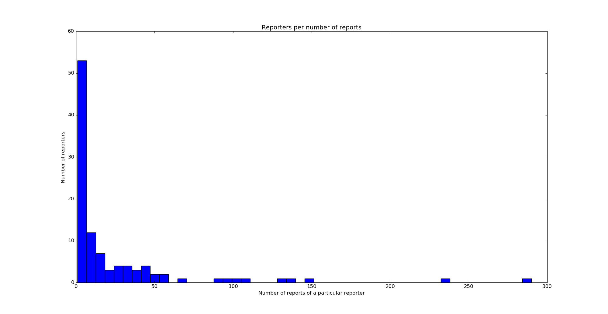
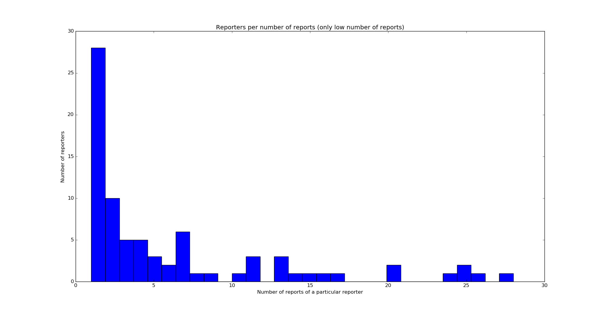
As an indication of the statistical significance of this test, I can say that a total of 2518 reports coming from 104 different reporters have been used. Just looking at these numbers is very far from doing a proper hypothesis contrast, but it is indicative that I have used a good amount of data. It is also interesting to look at the distribution of the number of reports given by each reporter. This is shown in the two histograms below (first for all numbers of reports and then for 30 reports and less).
The Python script and data used in this post are in this gist.
Lately, I have been trying to make an amplitude and phase calibration of my Hermes-Lite 2 beta2 in order to use Linrad’s smart noise blanker. This is quite a task because Linrad doesn’t support the Hermes-Lite 2 directly. Today I’ve finally managed to do it. Here I describe all my setup and calibration results.
Leif’s generator is very simple. It uses a 555 timer to generate a square wave, a 74AC74 flip-flop to divide the frequency of the square wave by 2 and obtain a precise 50% duty cycle, a 74AC04 inverter as a driver, and capacitive coupling to turn the edges of the square wave into RF pulses. Alex’s SIGP-1 is an improvement over Leif’s design. It generates the square wave in the same manner, but then it uses a helical bandpass filter for 144MHz with around 5MHz bandwidth to convert the square wave into 144MHz pulses, and a PGA-103+ MMIC RF amplifier and a BFR91 RF NPN transistor as a class A amplifier to increase the output level. The SIGP-1 has two main advantages over Leif design. The output is stronger, so the S/N of the pulses is higher, and the filtering helps prevent saturation in the receiver. However, Leif’s design uses only simple components and it’s adequate in many cases.
I have built and tested Leif’s generator and used it to calibrate my FUNcube Dongle Pro+ at 144MHz. I’ve also tried doing the calibration at other frequencies and it also works well, but the pulses are not very strong at 432MHz and above.
In some of the latest posts, I’ve being talking about the phase noise performance of 10GHz receivers, and in particular, of 27MHz references for Ku-band LNBFs (1, 2, 3, 4). Indeed, this started when I checked the performance of my new 10MHz GPSDO and 27MHz PLL by DF9NP and I wasn’t too happy with the phase noise.
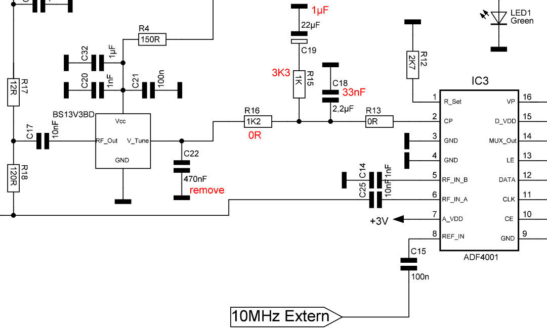
After working with Dieter DF9NP in investigating this problem and performing several tests, Dieter found that the problem was likely in the loop bandwidth of the 27MHz PLL. The loop filter bandwidth is 50kHz. He proposed the following component modifications to change the bandwidth to 300Hz.
Update 2018-10-21: Dieter tells me that this problem has been solved in the new units he is selling, so the performance of the new units should be good.
Modification of the PLL loop filter (new values in red)
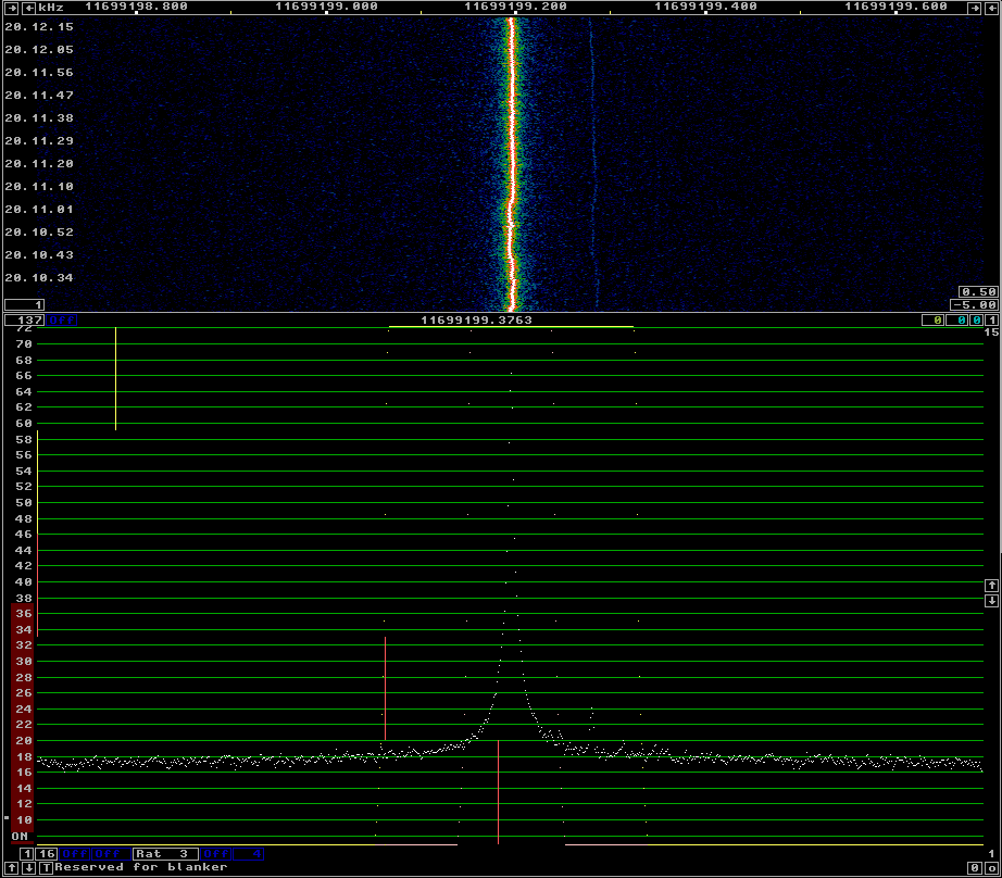
After I performed the modifications, I was quite surprised and happy with the results. As always, I’ve used the beacon of BADR-5 at 11966.2MHz to test the phase noise performance. Linrad’s AFC is in use. The result is below. As you can see, it is as good as the best references that I had tested before.
10MHz GPSDO and modified 27MHz PLL
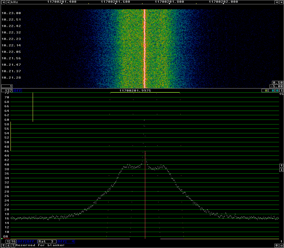
For comparison, this was the performance before the modification. The difference is huge. Many thanks to Dieter for his effort and to Luis EA5DOM, who also participated in the discussion and gave some good advice.
This is a follow up to a previous post where I investigated the phase noise of 27MHz references to be used for a 10GHz receiver. Dieter DF9NP has being kind enough to send me a 10MHz 0.25ppm TCXO to do some more tests.
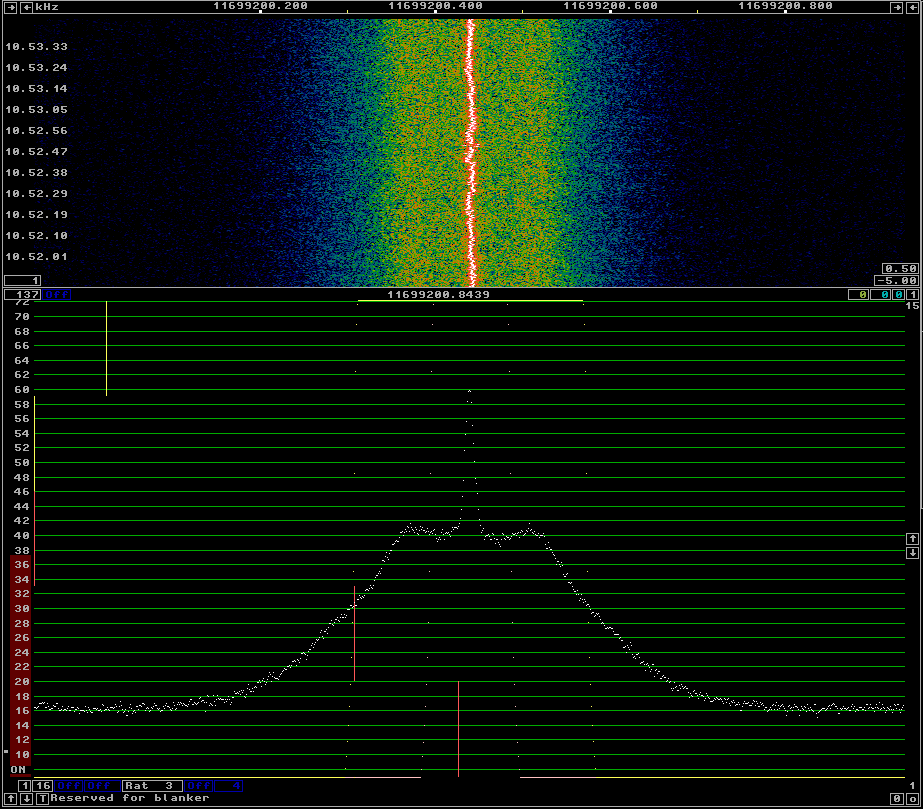
I’ve connected the 10MHz TCXO to the DF9NP 27MHz PLL and used it to receive the beacon of BADR-5, as I did in the previous post. The phase noise of the 10MHz TCXO + 27MHz PLL can be seen in the following figure.
10MHz 0.25ppm TCXO and 27MHz PLL
For comparison, see below the phase noise with the DF9NP 10MHz GPSDO and 27MHz PLL. There is not much difference between both. This seems to indicate that the culprit of the phase noise is the 27MHz PLL, as the 10MHz TCXO should be quite clean.
Today, I’ve being measuring the phase noise of the different 27MHz references that I have for my Ku-band LNBF. The LNBF is an Avenger PLL321S-2. I’ve modified it, removing the 27MHz crystal and including a connector for an external 27MHz reference signal. In my lab, I have the following equipment to generate a 27MHz signal:
OCXO/Si5351A kit. This kit includes a 27MHz OCXO and a Si5351A frequency synthesizer. The Si5351A can act as a buffer and output the OCXO signal directly or generate a 27MHz clock.
A DF9NP 27MHz PLL and a DF9NP GPSDO. The GPSDO generates a 10MHz signal which is locked to GPS. The PLL generates a 27MHz from the 10MHz signal.
I’ve used linrad to receive the beacon of BADR-5 at 11966.2MHz using different references for the 27MHz signal. The AFC in linrad tries to compensate for any drift in the reference or the satellite beacon. By averaging, one can get good plots of the sideband noise of the beacon. This is far from a proper lab test, but it gives a good idea of the performance of the references.
I’m using a OCXO/Si5351A kit as an external 27MHz reference for my LNBF-based 10GHz receiver. At first, I intended to use a buffer amplifier to take out directly the 27MHz cyrstal oscillator in the kit. However, I finally configured the Si5351A to generate 27MHz, as that was simpler.
Taking a look today at the documentation for the Si5351, I’ve realised that it is possible to configure the Si5351 to connect some of its outputs directly to the crystal oscillator input, acting as a buffer and bypassing all the frequency synthesis stages. To do this, XO_FANOUT_EN, which is bit 6 in register 187 “Fanout enable”, must be set to 1. The selector CLKn_SRC, which is bits 3 and 2 of clock control register (registers 16-23), is set to 00 (XTAL source) on reset, so this is already set correctly. It is probably a good idea to set CLKn_IDRV to 11 to get the highest drive strength on the output pin.