Some posts ago, I spoke about the possibility of using the OCXO/Si5351A synth kit from QRP Labs as a low cost way of providing an external stable 27MHz reference to a satellite LNBF. I’ve received and built my kit some days ago, so here I will be looking at some aspects in the construction and performance of this kit.
The assembly manual is very detailed and helpful, so there is not much I can say in this aspect. One needs build three boxes by soldering together pieces of PCB. This process is a bit time consuming, but I actually found it to be easy. I could solder all the pieces by hand without using blu-tack or any other tool to hold the pieces together while soldering. I just followed the instructions more or less, and tinned one corner in both pieces and then tacked them together. While tacking, you have one free hand, so you can move things around until everything is well aligned. Then I tacked the other corner, and finally soldered the whole seam.
In the oven, five components are held together closely so that they are in good thermal contact: the crystal, two MOSFET transistors used as a heater, a BJT used as a temperature sensor, and a BJT used in the crystal oscillator. I added some heatsink compound to these components to further improve thermal contact, as the next figure shows.
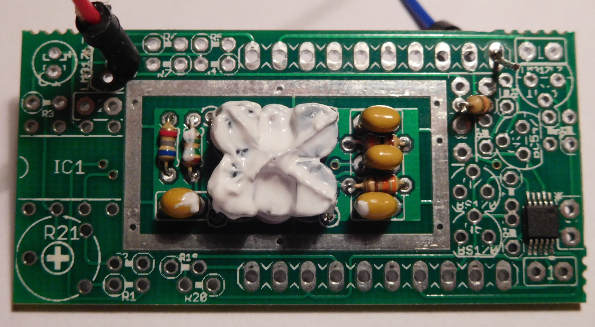
The components in the kit are quite packed together, but since everything is through-hole, they’re quite easy to solder. Just be sure to follow the instructions so that you solder the components in the correct order, because fitting the components in a different order can be much more difficult.
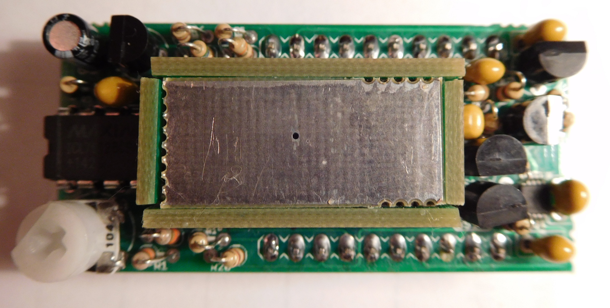
I filled the space between the oven box and the outer box with cotton wool to improve thermal isolation, taking care to leave the space for the adjustment potentiometer free. This tip is taken from Alan G8LCO and is listed on the kit’s web page. Be sure to read the whole page, as there are some other tips and mods you may want to do.
I still have to install the kit in some aluminium project box. There, I’ll have to include a 5V linear regulator, since I want to run everything from 13.8V, and a buffer amplifier to take the 27MHz signal out. I will probably also include connections for the I2C bus and one of the Si5351A outputs in case I want to use this for other things. By now, I have everything running on a breadboard to do some preliminary tests. I’ve even done some tests feeding the 27MHz to the LNBF and it works fine.
I have also done some tests adjusting the oven temperature, although the adjustment will vary once the kit is installed in its final form. The crystal oscillation frequency depends on the temperature and it has a minimum around 45ºC. The goal is to heat the crystal to this temperature, so that the frequency dependence on temperature will be smaller (mathematically, this is just because the derivative vanishes at the minimum). There are several methods on the kit’s web that you can try. The one that worked best for me is the following: first start with the adjustment potentiometer fully counter-clockwise, so that no heating is applied. Move the adjustment clockwise a bit and note how the oscillation frequency decreases as the crystal temperature raises. When the frequency gets stable or even increases slightly, move the adjustment clockwise again to further heat the crystal. This procedure has to be repeated until the frequency increases after moving the adjustment clockwise. This means that we’ve already moved past the minimum point, so the temperature should be backed off a bit by moving the adjustment counter-clockwise slightly. The crystal can take several minutes to get to the new temperature after each adjustment change, so this process can easily become very lengthy.
In the firsts tests I’ve made, the frequency accuracy seems as good as announced, on the order of 1ppb over a couple minutes. This is just a very rough estimate, because I don’t have a good enough frequency standard to make this kind of measurements, so I’ve been using my FT-817ND, which is fitted with a TCXO. I also tested the Si5351A. The easiest way to do this is probably to use an Arduino board and the demo code for Arduino. I just used an Arduino micro, which I could install on the same breadboard. The I2C bus doesn’t need external pull-up resistors, as this are included in the kit (together with 5V/3.3V level translation).
In the future, when I have installed the kit in its final form, I will be doing some experiments about its performance and how good it is as a 27MHz reference for a LNBF.
2 comments