A few days ago I tried to measure the QO-100 NB transponder LO stability using my DF9NP 10MHz GPSDO. It turned out that my GPSDO was less stable than the LO, so my measurements showed nothing about the QO-100 LO. Carlos Cabezas EB4FBZ has been kind enough to lend me a Vectron MD-011 GPSDO, which is much better than my DF9NP GPSDO and should allow me to measure the QO-100 LO.
Before starting the measurements with QO-100, I have taken the time to use the Vectron GPSDO to measure the Allan deviation of my DF9NP GPSDO over several days. This post is an account of the methods and results.
The DF9NP GPSDO is based on a 10MHz VCTCXO phased locked to an 800Hz signal coming from an uBlox LEA-4S GPS receiver. Since it doesn’t use an OCXO, it is inexpensive, doesn’t use much power and locks relatively fast. However, its stability is not as good as that of an OCXO-based GPSDO. In my experiments with QO-100 I measured an Allan deviation of \(10^{-10}\) for \(\tau\) between 1 and 10 seconds, which is typical of a TCXO.
The Vectron GPSDO that I’m using is the C6300 series evaluation kit for the MD-0113-BXJ-DAOC. Its datasheet advertises an Allan deviation of \(10^{-11}\) for \(\tau = 1\mathrm{s}\) and \(2\cdot 10^{-11}\) for \(\tau = 10\mathrm{s}\), and great holdover characteristics. It has been running for a couple of days before the start of the experiment, and so it has surveyed in the position of my GPS antenna and it is using a fixed position for its navigation solution.
Both GPSDOs are connected to the same GPS antenna via an (improperly terminated) T-connector. The antenna is a simple patch antenna and is located in a less than ideal position, near the ledge of a north-facing window, so it has only partial view of the southern sky.
I am using a LimeSDR-USB to compare the phases of the GPSDOs 10MHz outputs. To do so, the DF9NP GPSDO 10MHz output is used as an external reference in the LimeSDR as described in this post. The 10MHz output of the Vectron GPSDO is connected to the RF input of the LimeSDR through sufficient attenuation. This attenuation is provided by a Mini-Circuits ZFDC-10-1 directional coupler as follows: the OUT port is connected to the GPSDO 10MHz output, the IN port is terminated with a 50 Ohm load, and the CPL port is connected to the LimeSDR-USB. This is another less than ideal solution, but it gives lots of attenuation.
The LimeSDR-USB is tuned to 9.9MHz with a sample rate of 2Msps. This is possible by setting the LO to 30MHz, running with 32x oversampling, so the DAC rate is 64Msps, and using the NCO at -20.1MHz. This allows us to receive the 10MHz signal from the Vectron GPSDO at 100kHz in the IQ baseband.
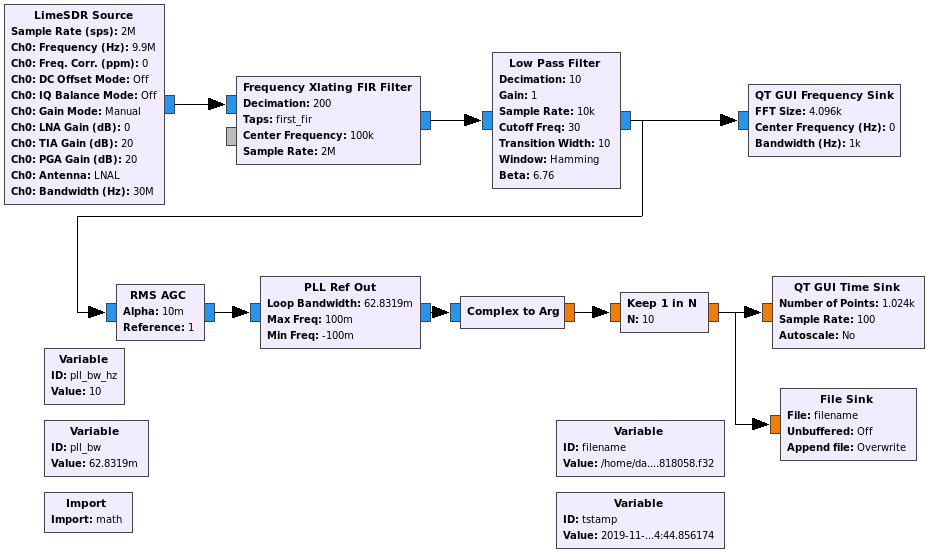
A GNU Radio companion flowgraph is used to lock a PLL to the signal and take phase measurements. A bandwidth of 10Hz is used for the PLL and the phase measurements are taken at a 100Hz rate. These are saved to disk for later analysis. The GRC flowgraph can be downloaded here and is shown in the figure below.
According to the phase measurements, the Vectron GPSDO signal is not exactly at 10MHz. There is an error of approximately 0.168mHz. This is caused by the frequency synthesizers of the LimeSDR: the ADF4002 doesn’t multiply the 10MHz reference coming from the DF9NP GPSDO by 30.72 exactly to yield the 30.72MHz LMS7002M clock, and likewise, the LMS7002M doesn’t multiply its 30.72MHz clock exactly by 30/30.72 to yield the 30MHz LO. Moreover, the NCO doesn’t run exactly at -20.1MHz, and the sample rate is not exactly 2MHz. Therefore, the 10MHz signal from the Vectron ends up with some small frequency error in the IQ baseband. This doesn’t affect the Allan deviation, however, so we will ignore this effect in the rest of this post.
The measurements were done between 2019-11-17 21:55 and 2019-11-20 18:15 UTC. However, there are phase jumps around 2019-11-20 04:58:00 UTC, most likely because the DF9NP GPSDO lost GPS lock at that moment. For simplicity, only the segment of measurements between 2019-11-17 21:55:31 and 2019-11-20 04:57:30 is used in the analysis. This amounts to almost 200000 seconds worth of measurements.
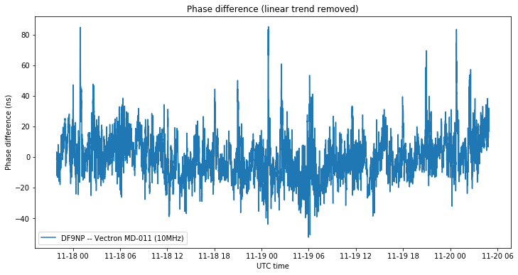
The figure below shows the phase difference between the two 10MHz signals after removing the linear drift caused by the instrumental 0.168mHz offset. The RMS phase difference is 14ns, and occasionally we get differences up to 80ns. This is well in line with the usual performance of the 1PPS (or other timepulse signal) of a non-timing-grade GNSS receiver, so we can expect this kind of performance from the DF9NP GPSDO.
The figure below shows the Allan deviation computed using the method of overlapping segments. In blue we show the measurements obtained in this post, while in orange we show a clock comparison between the DF9NP GPSDO and the GPSDO at the QO-100 groundstation in Bochum (Germany) done over the QO-100 NB transponder as described in this post. Both traces measure the performance of the DF9NP GPSDO, since the Vectron and the Bochum GPSDOs are much better.
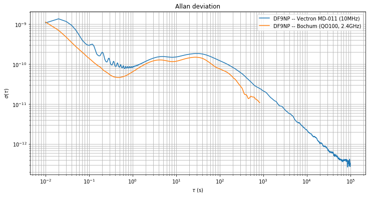
The same kind of behaviour appears in both traces, although the orange trace is slightly lower. This might be caused by the different instrumental setup used in each of the measurements. The blue trace was obtained at an observation frequency of 10MHz, while the orange trace was obtained at an observation frequency of 2.4GHz using an S/X satellite link.
The longer measurement span done in this post shows the Allan deviation up to \(\tau = 10^5\mathrm{s}\). We see that for \(\tau > 10^2\mathrm{s}\) the GPS disciplination kicks in and the Allan deviation decreases by an order of magnitude per decade. Between \(\tau = 1\mathrm{s}\) and \(\tau = 10^2\mathrm{s}\) we see an Allan deviation around \(10^{-10}\), dominated by the stability of the TCXO.
The calculations and figures in this post have been done in this Jupyter notebook.
This is very useful to me. Thank you for taking the time to post it! 🙂