I have made a mains choke for my HF station, following Ian GM3SEK’s design, which involves twisting the three mains wires together and passing as many turns as possible through a Fair-Rite 0431177081 snap-on ferrite core. I wanted to measure the choke’s impedance to get an idea of its performance, so I’ve used my Hermes-Lite 2.0 beta2 in VNA mode.
Category: Test equipment
Use, performance and testing of lab test equipment.
Update on phase noise of 27MHz references
This is a follow up to a previous post where I investigated the phase noise of 27MHz references to be used for a 10GHz receiver. Dieter DF9NP has being kind enough to send me a 10MHz 0.25ppm TCXO to do some more tests.
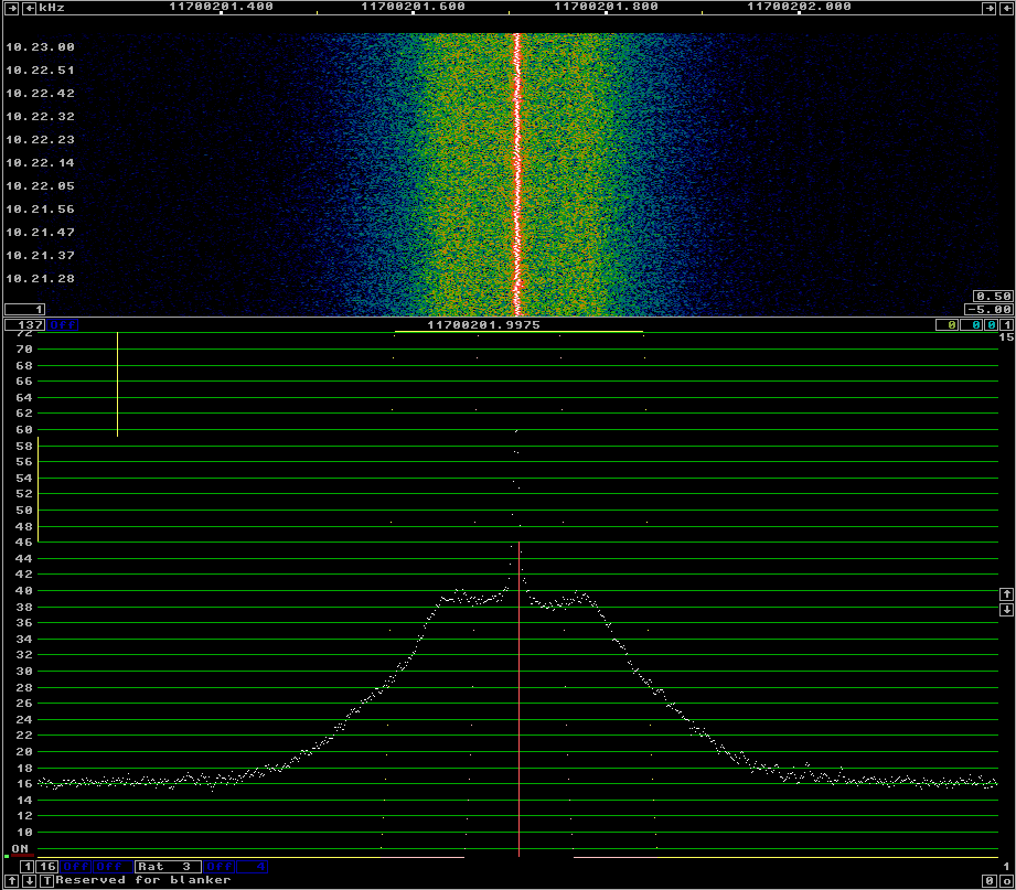
I’ve connected the 10MHz TCXO to the DF9NP 27MHz PLL and used it to receive the beacon of BADR-5, as I did in the previous post. The phase noise of the 10MHz TCXO + 27MHz PLL can be seen in the following figure.
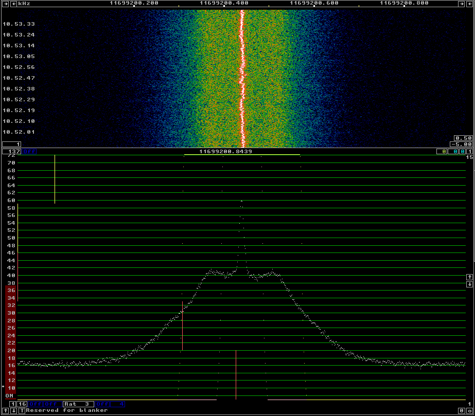
For comparison, see below the phase noise with the DF9NP 10MHz GPSDO and 27MHz PLL. There is not much difference between both. This seems to indicate that the culprit of the phase noise is the 27MHz PLL, as the 10MHz TCXO should be quite clean.
Phase noise of 27MHz references for a Ku-band LNBF
Today, I’ve being measuring the phase noise of the different 27MHz references that I have for my Ku-band LNBF. The LNBF is an Avenger PLL321S-2. I’ve modified it, removing the 27MHz crystal and including a connector for an external 27MHz reference signal. In my lab, I have the following equipment to generate a 27MHz signal:
- OCXO/Si5351A kit. This kit includes a 27MHz OCXO and a Si5351A frequency synthesizer. The Si5351A can act as a buffer and output the OCXO signal directly or generate a 27MHz clock.
- A DF9NP 27MHz PLL and a DF9NP GPSDO. The GPSDO generates a 10MHz signal which is locked to GPS. The PLL generates a 27MHz from the 10MHz signal.
I’ve used linrad to receive the beacon of BADR-5 at 11966.2MHz using different references for the 27MHz signal. The AFC in linrad tries to compensate for any drift in the reference or the satellite beacon. By averaging, one can get good plots of the sideband noise of the beacon. This is far from a proper lab test, but it gives a good idea of the performance of the references.
Calibrating the S-meter in Linrad
In a previous post, I talked about the GALI-39 amplifier kit from Minikits. Here I will describe the procedure to calibrate the S-meter in Linrad (or another SDR) using this amplifier or any other amplifier with a known NF and an uncalibrated signal source. Leif Åsbrink has a youtube video where he speaks about the calibration of the S-meter in Linrad. However, he doesn’t use an amplifier, so I will be following a slightly different procedure.