The GALI-39 is a DC-7GHz MMIC amplifier from Minicircuits. This device has a gain around 20dB and a NF of about 2.4dB. The nice thing about MMICs is that their input and output impedances are matched to 50Ω, so it’s quite easy to work with them. Minicircuits makes many MMIC amplifiers suiting different needs, but unfortunately their products are not so easy to get in small quantities.
Minikits.com.au is an Australian store that sells Minicircuits parts in small quantities as well as many interesting RF kits. I needed some RF amplifier having a known NF to do some signal level calibrations, so I ended up ordering the GALI-39 amplifier kit from Minikits. This kit includes just the GALI-39, a PCB and the handful of SMD components you need to bias the amplifier. At 22AUD, the price of the kit is about right and buying the kit instead of just the GALI-39 saves me to do the shopping for the assorted SMD components and using the PCB instead of botching some circuit is always nice, because the PCB uses microstrip transmission line (but the substrate is regular FR-4). Here I have a look at what is included in the kit (I’ve been unable to find a complete list on Minikit’s web).
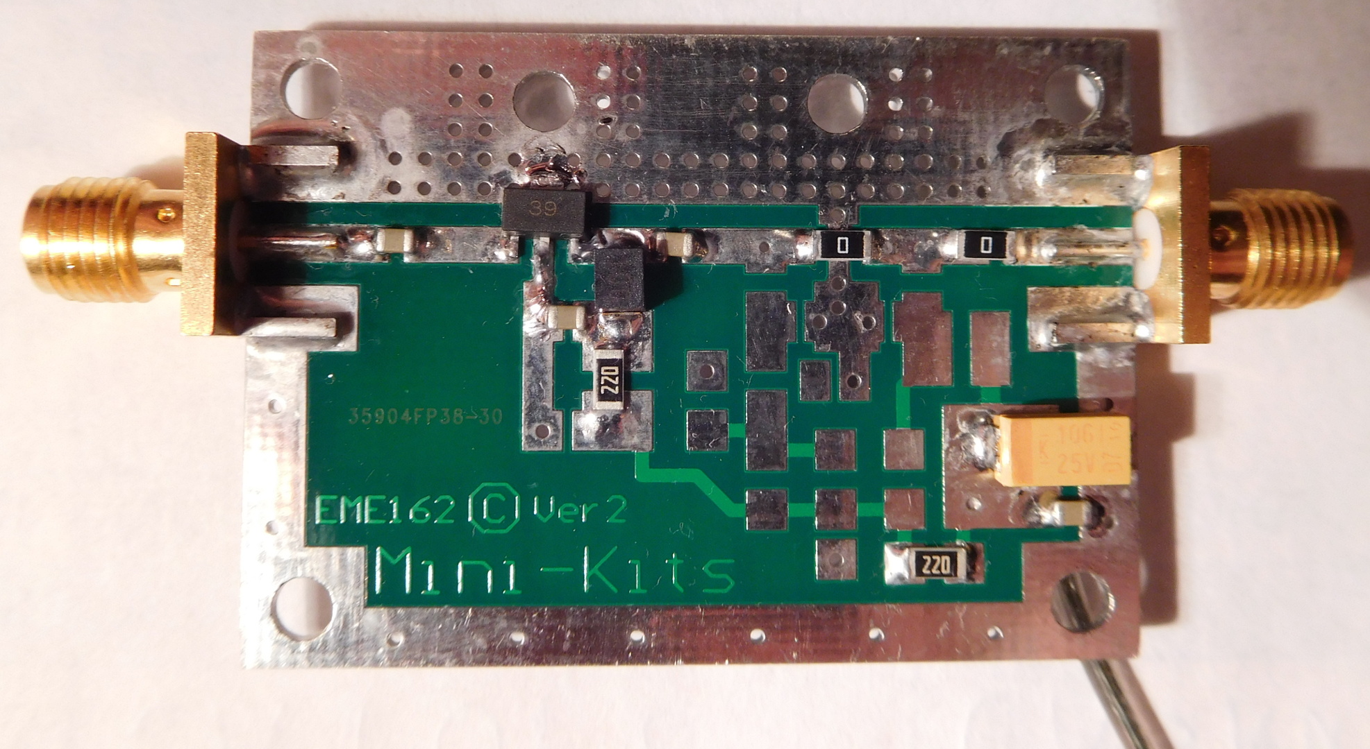
The kit is built on the EME162 PCB. This is a PCB design from Minikits that suits a number of different RF projects, most of them consisting of amplifier blocks. The board can accommodate an MMIC device (different packages are supported) and its respective bias and attenuator or filter networks. It’s actually quite a clever design. While it is the base of a number of kits from Minikits, it can also serve for many other simple projects that one may come up with.

The biasing for the GALI-39 is simple. Vcc is fed to the output pin through a bias resistor in series with an RF choke. In the kit, Vcc is 5V, provided by a 78M05 regulator. Two 22Ω resistors in series are used as a bias resistor. There is also a bypass capacitor to ground between the RF choke and the resistors.
The value of the RF choke, bypass capacitor and input and output decoupling capacitors is to be chosen in terms of the intended frequency of operation. The kit can be built for any of the following three frequency ranges: 500kHz-850MHz (0.1uF capacitors and 10uH choke), 50MHz-2GHz (100pF capacitors and 100nH choke) and 300MHz-4GHz (10pF capacitors and 22nH choke). Components are included the kit for all the three different ranges, together with some spare capacitors. Since I wanted to use my amplifier for HF, I built the first frequency range. This covers all the amateur bands from 160m to 70cm, so it is the most logical choice for amateur use unless the device is going to be used for the microwave bands.
The MMIC can be installed in two different positions: near the input connector or near the output connector. If the kit is going to be used as a receive preamplifier, then the MMIC should be installed near the input connector to obtain the best possible NF. If the kit is going to be used as a TX driver, then the MMIC should be installed near the output connector. Resistors for two optional pi attenuators are included in the kit: 5dB (two 180Ω shunt resistors and a 33Ω series resistor) and 10dB (two 100Ω shunt resistors and a 68Ω series resistor). They should only be used in case the gain of the MMIC is too large for a particular application.
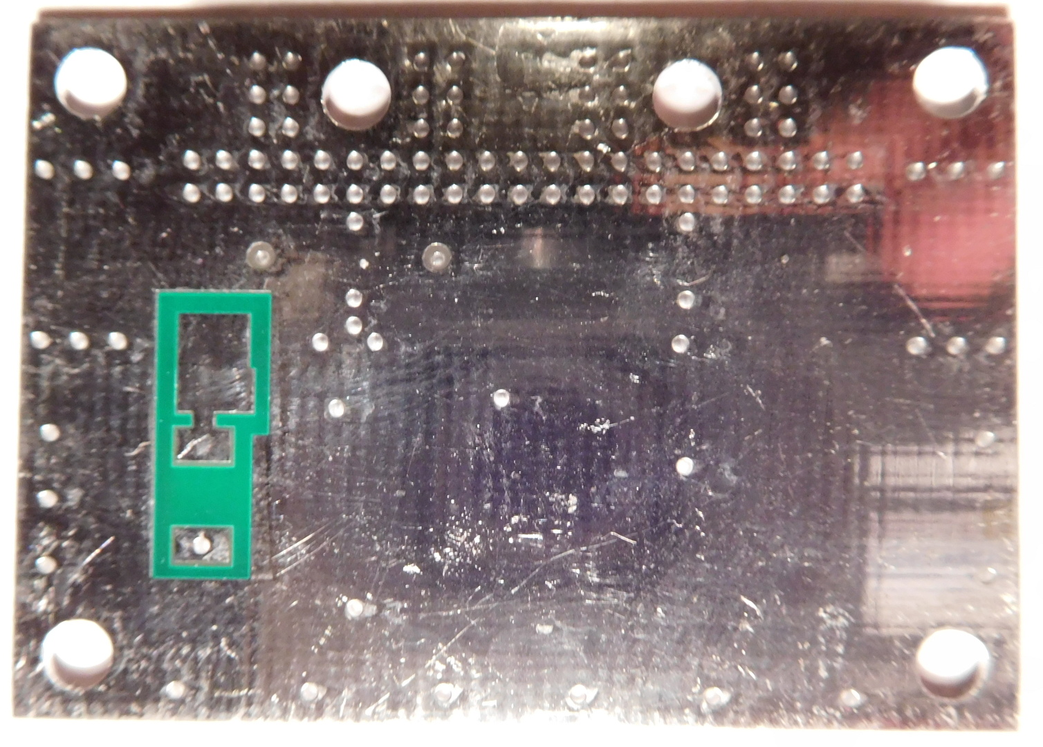
The remaining part of the kit is the voltage regulator, which is installed on the back of the PCB with its 1uF input bypass capacitor. The output of the regulator is bypassed with a 0.1uF capacitor and a 10uF tantalum capacitor. Both of them are installed on the front of the PCB. A piece of wire should also be soldered to the pad in the back of the PCB to provide +7 to +15VDC.

Altogether, the list of components included in the kit is:
- 3x 0R resistor
- 2x 22R resistor
- 1x 33R resistor
- 1x 68R resistor
- 2x 100R resistor
- 2x 180R resistor
- 3x 10pF ceramic capacitor
- 3x 100pF ceramic capacitor
- 6x 0.1uF ceramic capacitor
- 1x 1uF ceramic capacitor
- 1x 10uF tantalum capacitor
- 1x 22nH inductor
- 1x 100nH inductor
- 1x 10uH inductor
- 1x L78M05 (DPAK package)
- 1x GALI-39
PCB edge mount SMA connectors should be used with this kit. These can also be ordered from Minikits, but I didn’t do so, because that would have increased postage. If needed, an enclosure kit including RF and power connectors is also available, but I didn’t bother with it because I will be using my kit mainly for experimenting and I will probably modify it in the future.
2 comments