I’ve started to experiment with the RS92-SGP radiosonde that I recovered some days ago. The radiosonde has a M95256-W 32KB SPI EEPROM where all the code and settings are stored, since the onboard CPU/DSP doesn’t have any flash memory. Several parts of the firmware, including some of the settings have being reverse engineered. Thus, it is useful to interface the EEPROM to a microcontroller to rewrite some settings, perhaps to change the transmit frequency or the radiosonde’s ID (the serial number which is also printed on the radisonde’s box).
To access the EEPROM, one only needs to connect a microcontroller to the 4 SPI lines and hold the reset line of the onboard CPU to ground, to prevent the CPU from trying to talk to the EEPROM. These lines are all available in the card edge connector of the main board. Also, there is an unpopulated pin header near this connector that gives access to the same lines. You can do as me and solder a 3×2 pin header to get access to the SPI bus and the reset line. You can find more details about the pinouts in brmlab.
The only problem is that the EEPROM and the CPU I/O run at 2.85V. Connecting these lines to a 3.3V microcontroller is probably OK, but a 5V microcontroller can cause trouble. Péter has an Arduino sketch design to rewrite the frequency and transmit power. He reports that for him it works OK to connect a 5V Arduino directly. I tried to do the same and it didn’t work. The EEPROM didn’t respond to my commands. Nothing was damaged, however.
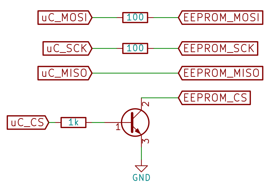
After a lot of troubleshooting, I started to suspect that the voltage levels where the problem. Therefore, I designed an appropriate level translator circuit. To do so, I first measured the state of the SPI lines when the onboard CPU is in reset mode. MOSI and SCK are driven low by a relatively low impedance (around 250 Ohms, but the I-V curve is very non-linear). Thus, these lines can be interface using a series resistor to make the voltage around 2.85V when the Arduino drives the line high to 5V. For me, 100 Ohm resistors worked fine.
The CS line is driven high by a relatively low impedance (around 300 Ohms, with non-linear I-V curve). A series resistor won’t work for this line, because if the resistor’s value is low, the voltage will be too high when the Arduino drives the line to 5V. If the resistor’s value is high, the voltage will not be near enough 0V when the Arduino drives the line low to ground. I couldn’t find a compromise value for a series resistor. What I did is to use an NPN transistor to pull the line to ground when it is needed and let the onboard CPU pull it high the rest of the time. The base of the transistor is connected to the Arduino CS pin through a suitable current limiting resistor. Note that the Arduino CS pin should be driven in an inverted way, but this is no problem, because I’m writing my own software.
Finally, the MISO line can be connected directly, because interfacing a 2.85V output to a 5V input directly works fine. The final result is as in the schematic below.
Using this, I’ve being able to write the EEPROM to change the radiosonde’s ID to my Amateur radio callsign (which will be necessary if I want to make the radiosonde to transmit on the Amateur bands). The radiosonde’s ID is stored in ASCII format in address 0x7018. It is 8 characters long. You can write spaces (0x20) over the unused characters.
I’ve also played with changing the frequency. This is stored in address 0x7002 as a little endian 16-bit unsigned integer. If the value of this field is x, the transmit frequency will be 400000 + 10*xkHz. However, you can’t get the radiosonde to transmit on 430MHz just by changing this value. There are reports that the maximum frequency you can get is 423MHz. For my unit, the maximum frequency is around 411MHz. At 411.5MHz the radiosonde needed some time to start transmitting and at 412MHz it didn’t work well. I’ll talk more about trying to change the transmit frequency in a future post.
Hi, nice project
did you worked further on? New insights?
tnx Alex
Hi Alex,
I haven’t worked any further with the RS92. Now I’ve started working with the newer RS41, which is an easier platform to use for modification projects, since it uses a standard STM32F microcontroller and other standard hardware instead of custom ASICs.