Recording DME with the LimeSDR

DME (distance measuring equipment) is an aircraft radio navigation system that is used to measure the distance between an aircraft and a DME station on ground. DME is often colocated with a VOR station, in which case the VOR provides the bearing information. DME works by measuring the two-way time of flight of pulse pairs, which are first transmitted by the aircraft, then retransmitted with a fixed delay by the ground station, which acts as a transponder, and finally received back by the aircraft. DME operates between 960 and 1215 MHz. It is channelized in steps of 1 MHz, and the air-to-ground and ground-to-air frequencies always differ by 63 MHz (here is a list of all the frequency channels).

I want to write a post explaining in detail how DME works by analysing a recording of DME that contains both the air-to-ground and the ground-to-air channels. Among other things, I want to show that the delay between the aircraft and ground station pulses matches the one calculated using the aircraft position (which I can get from ADS-B data on the internet), the ground station position, the position of the recorder, and the fixed delay applied by the ground station transponder.

Recording two channels 63 MHz apart is tricky with the kind of SDRs I have. Devices based on the AD9361 technically support a maximum sample rate of 61.44 Msps (although some people are running it at up to 122.88 Msps). The LMS7002M, which is used by the LimeSDR and other SDRs, is an interesting alternative, for two reasons. First, it supports more than 61.44 Msps. However, it isn’t clear what is the maximum sample rate supported by the LimeSDR. Some sources, including the LimeSDR webpage mention 61.44 MHz bandwidth, but the LMS7002M datasheet says that the maximum RF modulation bandwidth (whatever that means) through the digital interface in SISO mode is 96 MHz. In the case of the LimeSDR there is also the limitation of the USB3 data rate, but this should not be a problem if we use only 1 RX channel. I haven’t found clear information about the limitations of each of the components of the LMS7002M (ADC max sample rate, etc.).

The second interesting feature is that the LMS7002M has a DDC on the chip. The AD9361 has a series of decimating filters to reduce the ADC sample rate and deliver a lower sample rate through the digital interface. The LMS7002M, in addition to this, has an NCO and digital mixer that can be be used to apply a frequency shift to the ADC IQ signal before decimation.

I had two different ideas about how to use the LimeSDR to record the two DME channels. The first idea consisted in using a 70 Msps output sample rate. For this I used an ADC sample rate of 140 Msps, because I think it is necessary to have at least decimation by 2 after the ADC (the LMS7200M documentation does not explain this clearly, so figuring out how to use the chip often involves some trial and error using LimeSuiteGUI). This idea had two problems. The first problem is that some CGEN PLL occasionally failed to lock when using an ADC sample rate of 140 Msps. However the LimeSuite driver retried multiple times until the PLL locked, so in practice this wasn’t a problem. This approach worked well on my desktop PC, since in 70 Msps I had the two DME channels and then I could use GNU Radio to extract each of the two channels (for instance with the Frequency Xlating FIR Filter). However, the laptop I planned to use to record on the field couldn’t keep up with 70 Msps.

The second idea was to use the on-chip DDC in the LMS7200M to extract the DME channel and deliver a much lower sample rate over the digital interface. The figure below shows how the LMS7200M digital signal processing datapath works. This datapath is called RXTSP. The RXI and RXQ signals are the digital signals coming from the ADC (here and below, by ADC I mean a dual-channel ADC, since the LMS7002M is a zero-if IQ transceiver). The RYI and RYQ are the signals delivered to the digital interface of the chip. Since the LMS7200M has two RX channels, there are two identical chains, one for each channel. The parameters of each chain can be programmed completely independently.

LMS7200M digital signal processing, extracted from the datasheet

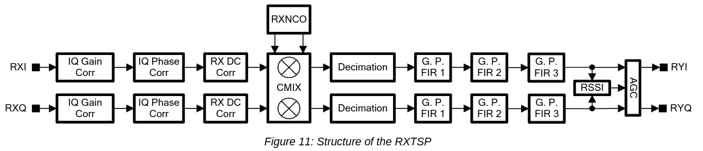
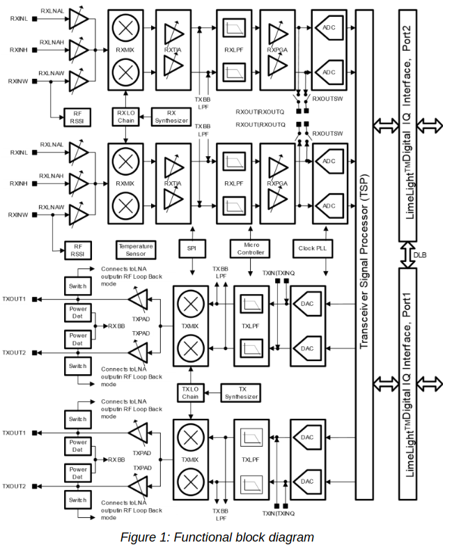
There is no way of sending the signal of one ADC to the two RXTSPs. The connection between each ADC and its corresponding RXTSP is fixed. Therefore, we need to feed in the antenna signal through the two RX channels, but we can easily do this with an external splitter. Remember that both of the LMS7200M RX channels share the same LO, as illustrated by the block diagram below. So the point here is to tune the LO to a frequency between the two DME channels, set the sample rate high enough that both DME channels are present in the ADC output, and finally to use each of the two RXTSPs to extract one of the DME channels, sending it at a low sample rate through the digital interface.

LMS7200M block diagram, extracted from the datasheet

This approach has worked quite well. I have set the ADC to 80 Msps and used the RXTSPs to dowconvert and decimate the DME channels to 2.5 Msps, recording that data directly in GNU Radio.

I have done a two hour recording of DME and published it in the Zenodo dataset Recording of Colmenar (CNR) VOR-DME air-to-ground and ground-to-air DME channels.

In the rest of this post I explain the details of the recording set up and do a preliminary analysis of the recording quality.

Ranging through the QO-100 WB transponder

One of the things I’ve always wanted to do since Es’hail 2 was launched is to perform two-way ranging by transmitting a signal through the Amateur transponder and measuring the round trip time. Stefan Biereigel DK3SB first did this about a year ago. His ranging implementation uses a waveform with a chip rate of only 10kHz, as it is thought for Amateur transponders having bandwidths of a few tens of kHz. With this relatively slow chiprate, he achieved a ranging resolution of approximately 1km.

The QO-100 WB transponder allows much wider signals that can be used to achieve a ranging resolution of one metre or less. This weekend I have been doing my first experiments about ranging through the QO-100 WB transponder.

Using an external reference with the LimeSDR Mini

A while ago I spoke about feeding an external reference to the LimeSDR USB. Now I wanted to use an external reference with the LimeSDR Mini that I have in my QO-100 groundstation to lock all the system to GPS. Preferably I wanted to use 27MHz as the reference, since this is what I am using in my LNB, so this would save me from having to run 10MHz or another frequency to the groundstation.

I wasn’t so sure how well this would work, since there are a few threads with questions in the MiriadRF forums, but I haven’t seen any explaining things in a clear way. There are different anecdotes of things that worked or didn’t work for several people, but not that many definitive answers. Among all the threads, this one seems mostly helpful.

Somewhat surprisingly, everything has worked well on the first try. I am now using a 27MHz external reference with my LimeSDR Mini. Hopefully this post will be of help to other people.

Software for my QO-100 groundstation

You may have heard about my groundstation for QO-100 (Es’hail-2), which is based on a BeagleBone black and a LimeSDR Mini. A description of this station appeared in a LimeSDR field report. However, I haven’t spoken in detail about the software yet, since I was testing various things and using a makeshift setup until I had some time to put together a solution that I really liked.

Now I am quite happy with the result and indeed I have decided to start up a Github repository with the software I am using in case anyone finds it useful. This post is a description of the software I am using for the narrowband transponder.

Transmitting through QO-100 with the LimeNET Micro and LimeRFE

A couple weeks ago, I did a demo where I showed the LimeRFE radio frequency frontend being used as an HF power amplifier to transmit WSPR in the 10m band. Another demo I wanted to do was to show the LimeNET Micro and LimeRFE as a standalone 2.4GHz transmitter for the QO-100 Amateur radio geostationary satellite.

The LimeNET Micro can be best described as a LimeSDR plus Raspberry Pi, so it can be used as an autonomous transceiver or remotely through an Ethernet network. The LimeRFE has a power amplifier for 2.4GHz. According to the specs, it gives a power of 31dBm, or a bit over 1W. This should be enough to work QO-100 with a typical antenna.

You may have seen the field report article about the QO-100 groundstation I have in my garden. It is based around a LimeSDR Mini and BeagleBone Black single board ARM computer. The groundstation includes a driver amplifier that boosts the LimeSDR to 100mW, and a large power amplifier that gives up to 100W. The LimeSDR Mini and BeagleBone Black give a very similar functionality to the LimeNET Micro, but the LimeNET Micro CPU is more powerful.

The idea for this demo is to replace my QO-100 groundstation by the LimeNET Micro and LimeRFE, maintaining only the antenna, which is a 24dBi WiFi grid parabola, and show how this hardware can be used as a QO-100 groundstation.

WSPR with the LimeRFE

A few days ago, I received a LimeRFE from Andrew Back of Lime Microsystems. He was kind enough to send me a unit so that I can test it and make some usage demos during the ongoing crowdfunding campaign at Crowd Supply.

The LimeRFE is intended to work as an RF frontend for the LimeSDR family, although it can work coupled with any other SDR or conventional radio. As such, it has power amplifiers, filters and LNAs designed to cover the huge frequency range of these SDRs. It is designed to cover all the Amateur radio bands from HF up to 9cm, and a few cellular bands.

As anyone will know, designing broadband RF hardware is often quite difficult or expensive (Amateur radio amplifiers and LNAs are usually designed for a single band), so packing all this into a single unit is a considerable feat. The output power on most bands is around a couple watts, which is already enough for many experiments and applications. The block diagram of the LimeRFE can be seen below.

LimeRFE block diagram

In this post I show a brief overview of the LimeRFE and demonstrate its HF transmission capabilities by showing a WSPR transmitter in the 10m band, using a LimeSDR as the transmitter.

Angle of arrival experiment in 145MHz

On April 28, I got together with a few Spanish radio Amateurs to perform some experiments. One of the things we did was an angle of arrival experiment in the 145MHz Amateur band. The ultimate goal of the experiment was to be able to measure the angle of arrival of meteor reflections of the GRAVES radar at 143.05MHz. However, we also recorded a few other signals, such as the Amateur satellite band at 145.9MHz (intended to perform calibration of the setup) and the APRS terrestrial signals at 144.8MHz.

Quick fixes for some bugs in LimeSDR drivers

These days I have been experimenting with my LimeSDR board. This is an SDR board based on the LMS7002M transceiver chip. The drivers for the LimeSDR are called LimeSuite. This bundle contains a SoapySDR driver called SoapyLMS7, which makes the LimeSDR accessible through SoapySDR and also in GNU Radio through gr-osmosdr; some lower level drivers for the LMS7002M chip; and a GUI called LimeSuiteGUI that allows one to play with all the settings and parameters of the LMS7002M by hand.

In my tests I have come across a couple of driver-related bugs which I find quite annoying. This is not surprising, as the LMS7002M is a very complex piece of hardware and the LimeSDR drivers must control a huge number of settings and parameters and provide different interfaces to access the SDR hardware. I have reported them in the GitHub issues page of LimeSuite, but there are many other bugs open and LimeSuite is still seeing heavy development, so it doesn’t look likely that they will be fixed very soon.

To overcome this bugs, I have done some workarounds. Rather than trying to find the root cause of the problem, these disable the part of the software that is not working as it should. These workarounds are in the dirtyfixes branch of my LimeSuite fork.

The first bug I found was related to the baseband filter. This filter has a selectable bandwidth. Some bandwidths didn’t work properly, because the passband was far from flat or the cut-off frequency was way off. Moreover, just changing the bandwidth slightly sometimes produced a very different filter shape. I have been tweeting some pictures showing this effect (see also my replies to this tweet). I’ve found that the reason for this is that the parameters to tune the filter are usually cached by the drivers in order to save computations, but this cache system doesn’t work properly. My workaround is to disable the cache and always compute the filter parameters.

The second bug is related to DC spur hardware removal. We are used to the fact that many IQ SDR hardware have a (sometimes huge) DC spur in the centre of the passband, due to several hardware imperfections. This is also the case for the LimeSDR, but the LMS7002M has a hardware system (called RX DC correction) which is quite effective at removing the DC spur. I noted that DC spur removal was much better in LimeSuiteGUI than in GNU Radio or SoapySDR based applications. You can see the difference here. At first, I thought that this was an issue with the IQ calibration. However, it turns out that the RX DC correction was always being disabled by the SoapyLMS7 driver, even though it was supposed to be enabled by default. The reason for this is that a lower-level function from the LMS7002M seems to lie and says that the RX DC correction is disabled, even though it is not. I have bypassed this lower-level function in my workaround. You can see the effects of RX DC correction here.

Update: The second bug has just been fixed. It seems that the DC_BY_RXTSP bit that controls the RX DC correction was being overwritten somewhere else in the TX setup code because of a typo. I have reverted the workaround in my “dirtyfixes” branch and merged the proper fix. This branch still contains the workaround for the lowpass filter calibration.