The Analog Devices AD9361 is an RFIC that is used in several popular SDRs, such as the USRP B2xx series and E3xx series, the BladeRF 2.0 micro, the ADALM Pluto, the ANTSDR, and in many other products (some of these use the AD9363 or the AD9364, which are similar chips in the same family). This RFIC has a nominal maximum sample rate of 61.44 Msps, and an analog bandwidth of 56 MHz.
A few days ago, Nuand has published a new software version that allows running the BladeRF 2.0 at 122.88 Msps. This has attracted some interest in Twitter, specially regarding questions about how they manage to achieve this and how good the performance is. One of the changes that Nuand has done to support the 122.88 Msps mode is an 8-bit wire protocol for the USB 3.0 interface. This is required to be able to pass 122.88 Msps through the USB. This change affects the FPGA gateware and host drivers. The other change involves manually setting some registers of the AD9361 in the host drivers in order to bypass a half-band filter, effectively doubling the output sample rate. In this post I will give a short review of the AD9361 register settings that enable the 122.88 Msps mode.
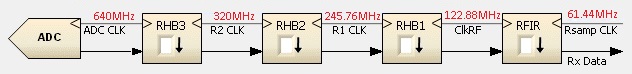
Before beginning, a word of caution: Analog Devices has a document which specifies the maximum rates along the data path of the AD9361. This includes the image shown below. The maximum output sample rate is 61.44 Msps. They state “please do not exceed below specified rates for the blocks shown”. In principle, running the device above these limits could not only cause a degradation in signal quality, but potentially permanent damage. On the other hand, Nuand mentions: “As is typical with overclocks, please bear in mind system stability may be affected. In our testing, we found the system to be quite stable.”
So, kids, don’t try this at home. If you test any of this, you’re doing so under your own responsibility.
In the 2023.02 bladeRF release, the code to set the AD9361 registers can be found in the bladerf_set_rational_sample_rate() function. The way this works is that first the AD9361 is configured for half of the desired frequency (for instance, for 61.44 Msps if we want to achieve 122.88 Msps). This is done using the regular code in the ADI no-OS AD9361 drivers, which among other things determines and sets the required configuration for the decimation stages in the RX chain. Afterwards, a few registers are set to some hardcoded values.
The code that sets the registers is listed below. I have commented it heavily, parsing out the values of each of the register fields and copying the relevant descriptions from the AD9364 register map reference. My comments are written with 3 slashes (///) so that they can be distinguished from the original comments in the bladeRF code.
Even though a couple dozen of registers are set, it is easy to summarize what they do. First, on the RX data path, RHB3 is set to decimate by 2, RHB2 is bypassed, RHB1 is set to decimate by 2 and RFIR is bypassed. This is what causes the sample rate to be twice its usual value. Normally, RHB2 would also be set to decimate by 2 in order to achieve the required RX data rate.
On the TX data path, all the interpolators are bypassed. I don’t understand how this is supposed to work. Usually, the DAC runs at the same frequency as the ADC or at half the frequency of the ADC (the maximum frequency supported by the DAC is lower than the maximum frequency supported by the ADC). In the RX data path the total decimation is 4. If we use no interpolation on the TX path, we would get a too high rate. Note that people have been testing mostly the 122.88 Msps RX, so maybe the TX doesn’t work as intended.
The next registers set a bunch of resistors and capacitors to manual control and set all the resistors to the highest value and the capacitors to the lowest value. I guess that the intention of this is to try to get around the usual limitation of 56 MHz bandwidth in the lowpass filter before the ADC. This seems a rather brute force approach. I wonder if better results could be obtained by tweaking the values.
Finally, the most mysterious part is that the 2 LSBs of the “BIST and Data Port Test Config” register are set to 0b11. According to the register map reference, these must be set to 0b00. I don’t know what is going on here, besides the fact that an undocumented feature is being used. Maybe this is necessary to make the digital interface go above 61.44 Msps.
I’ve done some very simple tests with one of the ADALM Plutos that I’m using to develop Maia SDR. When the Pluto is set up for 61.44 Msps rate, these are the data rates in the RX and TX paths:
# cat rx_path_rates
BBPLL:983040000 ADC:491520000 R2:245760000 R1:122880000 RF:61440000 RXSAMP:61440000
# cat tx_path_rates
BBPLL:983040000 DAC:245760000 T2:122880000 T1:61440000 TF:61440000 TXSAMP:61440000
The decimation/interpolation settings are governed by the registers 0x003 and 0x002, whose values are:
# iio_reg ad9361-phy 0x003
0x5c
# iio_reg ad9361-phy 0x002
0x58

/// - Rx Enable = 1
/// - RHB3 Enable and Decimation[1:0] = 1
/// - RHB2 Enable = 1
/// - RHB3 Enable = 1
/// - Rx FIR Enable and Decimation[1:0] = 0

/// - Tx Enable = 1
/// - THB3 Enable and Interpolation[1:0] = 1
/// - THB2 Enable = 1
/// - THB3 Enable = 0
/// - Tx FIR Enable and Interpolation[1:0] = 0
The remaining registers which are modified by the bladeRF 122.88 Msps mode have the following values:
# iio_reg ad9361-phy 0x0c2
0x1f
# iio_reg ad9361-phy 0x0c3
0x1f
# iio_reg ad9361-phy 0x0c4
0x1f
# iio_reg ad9361-phy 0x0c5
0x1f
# iio_reg ad9361-phy 0x0c6
0x1f
# iio_reg ad9361-phy 0x0c7
0x14
# iio_reg ad9361-phy 0x0c8
0x14
# iio_reg ad9361-phy 0x0c9
0x14
# iio_reg ad9361-phy 0x1e0
0x3
# iio_reg ad9361-phy 0x1e4
0xb2
# iio_reg ad9361-phy 0x1f2
0x0
# iio_reg ad9361-phy 0x1e6
0x1
# iio_reg ad9361-phy 0x1e7
0x0
# iio_reg ad9361-phy 0x1e8
0x7
# iio_reg ad9361-phy 0x1e9
0x0
# iio_reg ad9361-phy 0x1ea
0x7
# iio_reg ad9361-phy 0x1eb
0x0
# iio_reg ad9361-phy 0x1ec
0x7
# iio_reg ad9361-phy 0x1ed
0x2
# iio_reg ad9361-phy 0x1ee
0x60
# iio_reg ad9361-phy 0x1ef
0x2
# iio_reg ad9361-phy 0x3f6
0x0
Note however that many of these register values do not cause any effect because the BBF override bits are de-asserted. I have checked that setting register 0x1e0 to 0x83 instead of 0x03 in order to enable the RX BBF override causes an increase of approximately 4 dB in the signal level, but the passband shape doesn’t change. Therefore, the “manual” values of these override registers are not exactly the same ones that are being applied normally.
Setting the register 0x003 to 0x54 instead of 0x5c in order to bypass RHB2 seems to work, in the sense that the RX data path rates are computed accordingly.
# cat rx_path_rates
BBPLL:983040000 ADC:491520000 R2:245760000 R1:245760000 RF:122880000 RXSAMP:122880000
When this change is applied, there is definitely a change in the signals in the spectrum shown by Maia SDR. However, it is difficult to tell what is happening, since the Maia SDR FPGA design isn’t prepared to process IQ data at 122.88 Msps. The data path runs on a 62.5 MHz clock, so if the AD9361 supplies samples at 122.88 Msps, the FPGA will drop many samples. Changing from 31 Msps to 62 Msps by bypassing RHB2 appears to work correctly in Maia SDR.
There have been several examples of people on Twitter showing good results running the bladeRF above 61.44 Msps. However, no one has done yet some measurements of the RF performance, including bandpass response, out-of-band rejection, distortion (EVM, for instance) etc. It would be quite interesting to see a study of these parameters.
I don’t understand how the AD9361 provide a bandwidth of 56MHz with 61.44MSPS. Doesn’t this cause aliasing according to Nyquist–Shannon sampling theorem?
It is IQ (complex) sampling, so the Nyquist theorem says that the maximum representable bandwidth is equal to the sample rate (not half the sample rate as in real sampling).
Hi,
Just passing by to mention that the two bits set to 1 when the RM states they should be 00 appear in the AD9361 no-OS driver header file. They are, however, never explained or used throughout the code.
https://github.com/analogdevicesinc/no-OS/blob/885af0279fd8a2786eb1f4bd6dae5710665a77a7/drivers/rf-transceiver/ad9361/ad9361.h#L2791
what limits us to work in 122.88? why not go up to 245.76 or something aswell?
The fact that the chip is only designed to go up to 61.44 Msps, so even running it at 122.88 Msps is a stretch and things don’t work as well as they should.
Hey Daniel,
In the meantime, do you know of any RF performance measurements that have been done with the 122.88 MSPS mode?
Thanks
I haven’t seen any RF performance measurements.
Hey Daniel,
I was wondering if you had a repository with this test that I could see. I tried to reproduce it using maia-sdr but the timing doesn’t seem to match (I followed the ). I wanted to make some test and see how well it performs.
Thanks
Hi Freddy, I was doing this work in a throwaway manner. I don’t think I saved this to a repository.