More about the QO-100 WB transponder power budget

Last week I wrote a post with a study about the QO-100 WB transponder power budget. After writing this post, I have been talking with Dave Crump G8GKQ. He says that the main conclusions of my study don’t match well his practical experience using the transponder. In particular, he mentions that he has often seen that a relatively large number of stations, such as 8, can use the transponder at the same time. In this situation, they “rob” much more power from the beacon compared to what I stated in my post.

I have looked more carefully at my data, specially at situations in which the transponder is very busy, to understand better what happens. In this post I publish some corrections to my previous study. As we will see below, the main correction is that the operating point of 73 dB·Hz output power that I had chosen to compute the power budget is not very relevant. When the transponder is quite busy, the output power can go up to 73.8 dB·Hz. While a difference of 0.8 dB might not seem much, there is a huge difference in practice, because this drives the transponder more towards saturation, decreasing its gain and robbing more output power from the beacon to be used by other stations.

I want to thank Dave for an interesting discussion about all these topics.

Measuring the QO-100 WB transponder power budget

The QO-100 WB transponder is an S-band to X-band amateur radio transponder on the Es’hail 2 GEO satellite. It has about 9 MHz of bandwidth and is routinely used for transmitting DVB-S2 signals, though other uses are possible. In the lowermost part of the transponder, there is a 1.5 Msym QPSK 4/5 DVB-S2 beacon that is transmitted continuously from a groundstation in Qatar. The remaining bandwidth is free to be used by all amateurs in a “use whatever bandwidth is free and don’t interfere others” basis (there is a channelized bandplan to put some order).

From the communications theory perspective, one of the fundamental aspects of a transponder like this is how much output power is available. This sets the downlink SNR and determines whether the transponder is in the power-constrained regime or in the bandwidth-constrained regime. It indicates the optimal spectral efficiency (bits per second per Hz), which helps choose appropriate modulation and FEC parameters.

However, some of the values required to do these calculations are not publicly available. I hear that the typical values which would appear in a link budget (maximum TWTA output power, output power back-off, antenna gain, etc.) are under NDA from MELCO, who built the satellite and transponders.

I have been monitoring the WB transponder and recording waterfall data of the downlink with my groundstation for three weeks already. With this data we can obtain a good understanding of the transponder behaviour. For example, we can measure the input power to output power transfer function, taking advantage of the fact that different stations with different powers appear and disappear, which effectively sweeps the transponder input power (though in a rather chaotic and uncontrollable manner). In this post I share the methods I have used to study this data and my findings.

Monitoring the QO-100 WB transponder usage with Maia SDR

I am interested in monitoring the usage of the QO-100 WB transponder over several weeks or months, to obtain statistics about how full the transponder is, what bandwidths are used, which channels are occupied more often, etc., as well as statistics about the power of the signals and the DVB-S2 beacon. For this, we need to compute and record to disk waterfall data for later analysis. Maia SDR is ideal for this task, because it is easy to write a Python script that configures the spectrometer to a low rate, connects to the WebSocket to fetch spectrometer data, performs some integrations to lower the rate even more, and records data to disk.

For this project I’ve settled on using a sample rate of 20 Msps, which covers the whole transponder plus a few MHz of receiver noise floor on each side (this will be used to calibrate the receiver gain) and gives a frequency resolution of 4.9 kHz with Maia SDR’s 4096-point FFT. At this sample rate, I can set the Maia SDR spectrometer to 5 Hz and then perform 50 integrations in the Python script to obtain one spectrum average every 10 seconds.

Part of the interest of setting up this project is that the Python script can serve as an example of how to interface Maia SDR with other applications and scripts. In this post I will show how the system works and an initial evaluation of the data that I have recorder over a week. More detailed analysis of the data will come in future posts.

Using GSE and DVB-S2 for IP traffic

GSE (Generic Stream Encapsulation) is a protocol used to embed packets of almost any sort into the DVB data link layer. It can be used to send IP (IPv4 and IPv6) packets, Ethernet packets, etc. In my post about Blockstream Satellite, I talked about MPE, which is another way of sending IP traffic inside DVB. However, MPE is based on MPEG TS packets, so it is a far from ideal solution, given the overhead of the TS headers and the relatively small size of TS packets. GSE is a much more lightweight solution, and it’s arguably the best way of sending IP packets inside DVB.

The downside of GSE compared to MPE is that it is not supported by so many devices. Since MPE uses TS packets, it should be supported by mostly any device. The formatting of the TS packets, and thus all of the MPE stack, is handled at the application level. However, GSE is different from a stream of TS packets already the level of BBFRAMEs, so devices that handle this layer need to support GSE.

In this post I show how to set up a DVB-S2 GSE one-way link using the GNU Radio out-of-tree module gr-dvbgse and an SDR for transmission, and a MiniTiouner, Longmynd and some software I’ve written for reception.

The MiniTiouner is a DVB-S2 hardware receiver that is based on a Serit FTS4334 NIM (which uses the STV0910 DVB-S2 demodulator IC) together with a FT2232H that provides a USB2 interface for data and control. It is a very popular device within the Amateur TV community, given its affordable price and large range of supported carrier frequencies, symbol rates, and MODCODs.

The ideas in this post are also applicable to an SDR demodulation approach, which could use gr-dvbs2rx and gr-dvbgse. Using a hardware receiver solution can give some benefits over an SDR receiver, since demodulation and LDPC decoding is computationally expensive, specially at higher symbol rates and in low SNR conditions.

My final goal for this is to do some tests of two-way IP links over the QO-100 WB transponder. I think this would be a rather interesting use of the transponder, since it would open the door to many new ideas. Currently the transponder is used almost exclusively to transmit video, which by all means is good, but not very innovative after the almost 4 years now that the transponder has been in operation.

I have to give huge thanks to Brian Jordan G4EWJ and Evariste Courjard F5OEO for their interest in this project and for running many initial tests that showed that it is possible to use the MiniTiouner to receive GSE (despite the lack of clear and detailed documentation about the STV0910 register settings).
More QO-100 orbit determination

In a previous post, I showed my orbit determination experiments of the GEO satellite Es’hail 2 using the beacons transmitted from Bochum (Germany) through the QO-100 amateur radio transponder on-board this satellite. By measuring the phase difference of the BPSK and 8APSK beacons, which are spaced apart by 245 kHz in the transponder, we can compute the three-way range-rate between the transmitter at Bochum and my receiver in Spain. This data can then be used for orbit determination with GMAT.

I have continued collection more data for these experiments, so this post is an update on the results.

QO-100 orbit determination

In a previous post, I showed my experiment about measuring the phase difference of the 8APSK and BPSK beacons of the QO-100 NB transponder. The main goal of this experiment was to use this data to do orbit determination with GMAT. Over the last week I have continued these experiments and already have started to perform some orbit determination in GMAT.

Here I give an update about several aspects of the experiment, and show how I am setting up the orbit determination.

Measuring the QO-100 beacons phase difference

Since a couple months ago, the QO-100 NB transponder has now two digital beacons being transmitted continuously: the “traditional” 400 baud BPSK beacon, and the new 2.4 kbaud 8APSK multimedia beacon. This transponder is an amateur radio bent-pipe linear transponder on board the Es’hail 2 GEO satellite. It has an uplink at 2400.25 MHz, a downlink at 10489.75 MHz, and 500 kHz bandwidth. The two beacons are transmitted from the AMSAT-DL groundstation in Bochum, Germany, with a nominal frequency separation of 245 kHz.

In some posts in the last few years (see this, for instance), I have been measuring the frequency of the BPSK beacon as received by my grounstation in Madrid, Spain. In these frequency measurements we can see the daily Doppler curve of the satellite, which is not completely stationary with respect to the surface of Earth. However, we can also see the frequency variations of the local oscillator of the transponder (including some weird effects called “the wiggles“). For this reason, the frequency of the BPSK beacon is not an ideal measurement for orbit determination, since it is contaminated by the onboard local oscillator.

If we measure the frequency (or phase) of the 8APSK and BPSK beacons and subtract the two measurements, the effects caused by the transponder local oscillator cancel out. The two beacons have slightly different Doppler, because they are not at the same frequency. The quantity that remains after the subtraction is only affected by the movement of the satellite.

Bochum and my station use both references locked to GPS. Therefore, the phase difference of the two beacons gives the group delay from Bochum through the transponder to my station. This indicates the propagation time of the signal, which is often known as three-way range. The three-way range is roughly the sum of distances between the satellite and each groundstation (roughly, but not exactly, due to the light-time delay). It is a quantity that is directly applicable in orbit determination.

In this post I present my first results measuring the phase difference of the beacons and the three-way range.

Decoding the QO-100 multimedia beacon with GNU Radio: part II

In my previous post I showed a GNU Radio demodulator for the QO-100 multimedia beacon, which AMSAT-DL has recently started to broadcast through the QO-100 NB transponder, using a downlink frequency of 10489.995 MHz. This demodulator flowgraph could receive and save to disk the files transmitted by the beacon using the file receiver from gr-satellites. However, the performance was not so good, because it had a couple of ad-hoc Python blocks. Also, the real-time streaming data (which uses WebSockets) was not handled.

I have continued working in the decoder and solved these problems. Now we have a decoder with good performance that uses new C++ blocks that I have added to gr-satellites, and the streaming data is supported. I think that the only feature that isn’t supported yet is displaying the AMSAT bulletins in the qo100info.html web page (but the bulletins are received and saved to disk).

I have added the decoder and related tools to the examples folder of gr-satellites, so that other people can set this up more easily. In this post I summarise this work.

Decoding the QO-100 multimedia beacon with GNU Radio

Last weekend, AMSAT-DL started some test transmissions of a high-speed multimedia beacon through the QO-100 NB transponder. The beacon uses the high-speed modem by Kurt Moraw DJ0ABR. It is called “high-speed” because the idea is to fit several kbps of data within the typical 2.7 kHz bandwidth of an SSB channel. The modem waveform is 2.4 kbaud 8APSK with Reed-Solomon (255, 223) frames. The net data rate (taking into account FEC and syncword overhead) is about 6.2 kbps.

I had never worked with this modem before, even though it served me as motivation for my 32APSK modem (still a work in progress). With a 24/7 continuous transmission on QO-100, now it was the perfect time to play with the modem, so I quickly put something together in GNU Radio. In this post I explain how my prototype decoder works and what remains to be improved.

QO-100 spring eclipse season

A few days ago, the spring eclipse season for Es’hail 2 finished. I’ve been recording the frequency of the NB transponder BPSK beacon almost 24/7 since March 9 for this eclipse season. In the frequency data, we can see that, as the spacecraft enters the Earth shadow, there is a drop in the local oscillator frequency of the transponder. This is caused by a temperature change in the on-board frequency reference. When the satellite exits the Earth shadow again, the local oscillator frequency comes back up again.

The measurement setup I’ve used for this is the same that I used to measure the local oscillator “wiggles” a year ago. It is noteworthy that these wiggles have completely disappeared at some point later in 2020 or in the beginning of 2021. I can’t tell exactly when, since I haven’t been monitoring the beacon frequency (but other people may have been and could know this).

A Costas loop is used to lock to the BPSK beacon frequency and output phase measurements at a rate of 100 Hz. These are later processed in a Jupyter notebook to obtain frequency measurements with an averaging time of 10 seconds. Some very simple flagging of bad data (caused by PLL unlocks) is done by dropping points for which the derivative exceeds a certain threshold. This simple technique still leaves a few bad points undetected, but the main goal of it is to improve the quality of the plots.

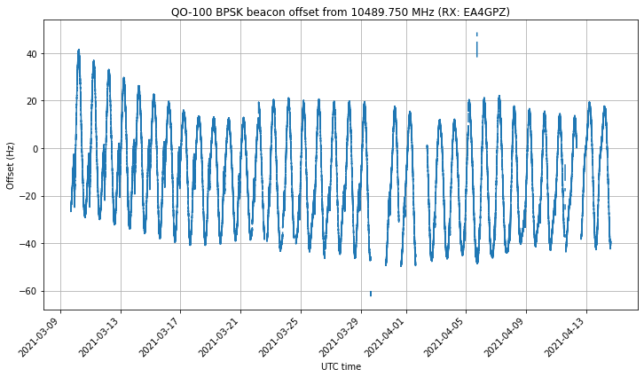
The figure below shows the full time series of frequency measurements. Here we can see the daily sinusoidal Doppler pattern, and long term effects both in the orbit and in the local oscillator frequency.

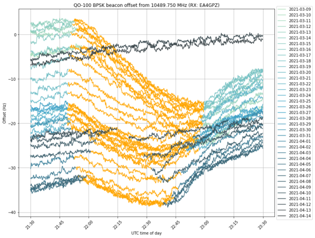
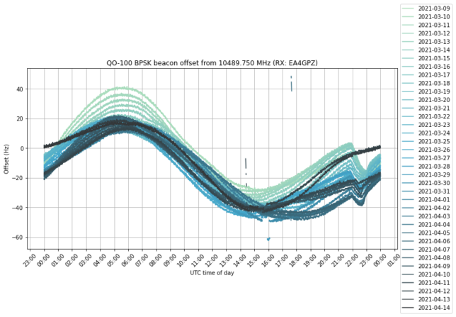
If we plot all the days on top of each other, we get the following. The effect of the eclipse can be clearly seen between 22:00 and 23:00 UTC.

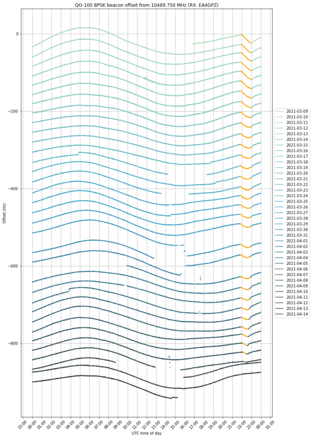
By adding an artificial vertical offset to each of the traces, we can prevent them from lying on top of each other. We have coloured in orange the measurements taken when the satellite was in eclipse. The eclipse can be seen getting shorter towards mid-April and eventually disappearing.

We see that the frequency drop starts exactly as soon as the eclipse starts. In many days, the drop ends at the same time as the eclipse, but in other days the drop ends earlier and we can see that the orange curve starts to increase again near the end of the eclipse. This can be seen better in the next figure, which shows a zoom to the time interval when the eclipse happens, and doesn’t apply a vertical offset to each trace. I don’t have an explanation for this increase in frequency before the end of the eclipse.

The plots in this post have been done in this Jupyter notebook. The frequency measurements have been stored in this netCDF4 file, which can be loaded with xarray.