These days I have been experimenting with my LimeSDR board. This is an SDR board based on the LMS7002M transceiver chip. The drivers for the LimeSDR are called LimeSuite. This bundle contains a SoapySDR driver called SoapyLMS7, which makes the LimeSDR accessible through SoapySDR and also in GNU Radio through gr-osmosdr; some lower level drivers for the LMS7002M chip; and a GUI called LimeSuiteGUI that allows one to play with all the settings and parameters of the LMS7002M by hand.
In my tests I have come across a couple of driver-related bugs which I find quite annoying. This is not surprising, as the LMS7002M is a very complex piece of hardware and the LimeSDR drivers must control a huge number of settings and parameters and provide different interfaces to access the SDR hardware. I have reported them in the GitHub issues page of LimeSuite, but there are many other bugs open and LimeSuite is still seeing heavy development, so it doesn’t look likely that they will be fixed very soon.
To overcome this bugs, I have done some workarounds. Rather than trying to find the root cause of the problem, these disable the part of the software that is not working as it should. These workarounds are in the dirtyfixes branch of my LimeSuite fork.
The first bug I found was related to the baseband filter. This filter has a selectable bandwidth. Some bandwidths didn’t work properly, because the passband was far from flat or the cut-off frequency was way off. Moreover, just changing the bandwidth slightly sometimes produced a very different filter shape. I have been tweeting some pictures showing this effect (see also my replies to this tweet). I’ve found that the reason for this is that the parameters to tune the filter are usually cached by the drivers in order to save computations, but this cache system doesn’t work properly. My workaround is to disable the cache and always compute the filter parameters.
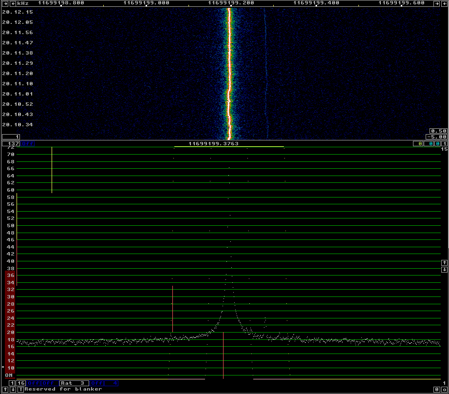
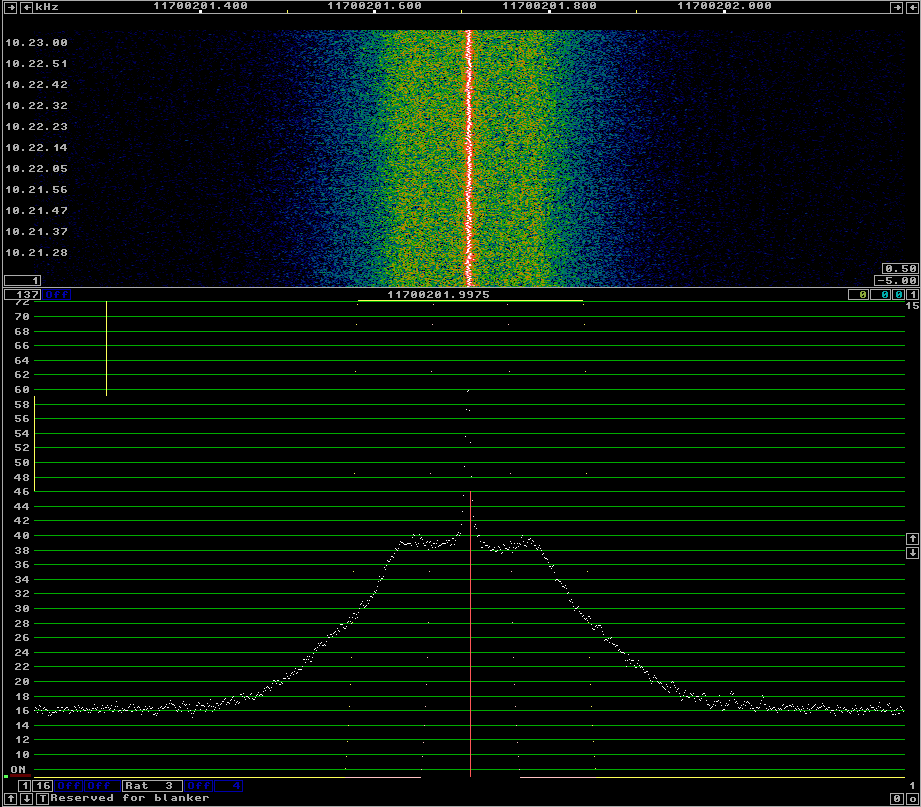
The second bug is related to DC spur hardware removal. We are used to the fact that many IQ SDR hardware have a (sometimes huge) DC spur in the centre of the passband, due to several hardware imperfections. This is also the case for the LimeSDR, but the LMS7002M has a hardware system (called RX DC correction) which is quite effective at removing the DC spur. I noted that DC spur removal was much better in LimeSuiteGUI than in GNU Radio or SoapySDR based applications. You can see the difference here. At first, I thought that this was an issue with the IQ calibration. However, it turns out that the RX DC correction was always being disabled by the SoapyLMS7 driver, even though it was supposed to be enabled by default. The reason for this is that a lower-level function from the LMS7002M seems to lie and says that the RX DC correction is disabled, even though it is not. I have bypassed this lower-level function in my workaround. You can see the effects of RX DC correction here.
Update: The second bug has just been fixed. It seems that the DC_BY_RXTSP bit that controls the RX DC correction was being overwritten somewhere else in the TX setup code because of a typo. I have reverted the workaround in my “dirtyfixes” branch and merged the proper fix. This branch still contains the workaround for the lowpass filter calibration.