In my previous post I set out to measure the phase difference between the QO-100 8APSK and BPSK beacons. One of the things I mentioned is that the frequency separation between these two beacons was approximately 1.6 Hz larger than the nominal 245 kHz.
A frequency error of a couple of Hz is typical when working with SDRs unless special care is taken. Many SDRs allow choosing the sample rate and centre frequency with great flexibility, but the drawback is that the frequencies that are achieved are often not exactly the ones we indicated. Fractional-N synthesis PLLs are used to generate the sampling clock and local oscillator, so there are small rounding errors in the generated frequencies.
With enough knowledge of how the SDR hardware works and how it is configured, it is possible to determine these frequency errors exactly, as a rational number \(p/q\) that we can calculate explicitly, multiplied by the reference frequency of the SDR. Then we can use this exact value to correct our measurements.
I have asked Mario Lorenz DL5MLO and Kurt Moraw DJ0ABR the details of how the beacons are generated in the Bochum groundstation. Two ADALM Pluto‘s are used: one generates the CW and BPSK beacons, and the other generates the 8APSK multimedia beacon. With the data they have given me, I have been able to compute the frequency separation of the 8APSK and BPSK beacons exactly, and the result matches well my experimental observations.
In this post we will look at how the fractional-N synthesis calculations for the Pluto can be done. Since the Pluto uses an AD9363 RFIC, these calculations are applicable to any product using one of the chips from the AD936x family, and to the FMCOMMS3 evaluation board.
AD936x frequency synthesis
Let us begin with a general discussion of how frequency synthesis works in the AD936x family, and how the relevant register values can be obtained when using the Linux kernel driver. The contents of this post apply to the AD9361, AD9363 and AD9364 chips, since the frequency synthesis works in the same way in all of them.
The AD936x uses an external reference or crystal. All the internal frequencies, including the sampling clock and local oscillators are derived from this reference. A typical reference frequency is 40 MHz. This is the value used in the ADALM Pluto and in the FMCOMMS3 board, although the chip supports a wider range of frequencies.
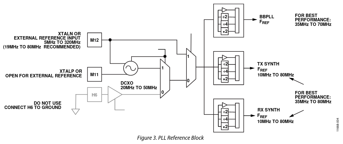
The AD9361 reference is used to generate references for the BBPLL, which is a PLL that will be divided to generate the sampling clock, and for RFPLLs, which are PLLs from which the RX and TX LOs are generated by division. For each of these, the reference can be divided by 2, by 4, multiplied by 2 or left unchanged.
The BBPLL is a fractional-N PLL with a denominator of 2088960, which equals \(2^{13}\cdot 3 \cdot 5 \cdot 17\). Its VCO can tune to a frequency between 715 and 1430 MHz. The relevant formulas for the frequency of this PLL are shown below.
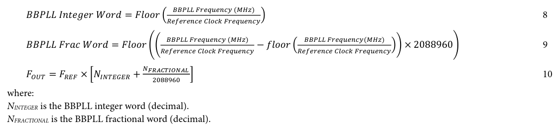
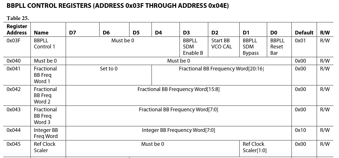
The registers for the BBPLL frequency synthesis are 0x41-0x45. Registers 0x41-0x43 contain the fractional word \(N_{FRACTIONAL}\), register 0x44 contains the integer word \(N_{INTEGER}\), and register 0x45 contains the scaler value applied to the AD936x reference to obtain the reference for the BBPLL (with the encoding 00: x1; 01: x½; 10: x¼; 11: x2).
Using the Linux kernel driver, these registers can be read with the iio_reg tool. For instance
# iio_reg ad9361-phy 0x41
shows the contents of register 0x41.
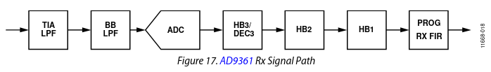
The BBPLL output is divided by a power of 2 between 2 and 64 to obtain the ADC clock. The DAC clock can either be the same as the ADC clock, or the ADC clock divided by 2.
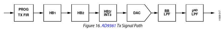
After the ADC (before the DAC) there is a chain of decimating (interpolating) filters, so the sample rate used on the external interface of the AD936x is typically lower than the rate at which the data converters run. The HB3/DEC3 (HB3/INT3) filter can decimate (interpolate) by 2 or 3, or be bypassed; the HB2 and HB1 filters can decimate (interpolate) by 2 or be bypassed; the FIR filter can decimate (interpolate) by 1, 2 or 4. Usually, the data converters are run at the highest possible sample rate, using the decimating (interpolating) filters to reduce the sample rate to what is required by the user.
The settings of all of these filters can be checked in the registers (0x02, 0x03, and 0x0A), but there is a quicker way to obtain this information. In /sys/bus/iio/devices there is a directory corresponding to the ad9361-phy (this can be checked in the name file inside the directory). This directory directory contains files rx_path_rates and tx_path_rates, which give the sample rates throughout the RX and TX chain. For instance, for a 1 Msps setting,
# cat tx_path_rates
BBPLL:1024000000 DAC:32000000 T2:16000000 T1:8000000 TF:4000000 TXSAMP:1000000
The values in these files are rounded, so the correct way to use these files is to compute the BBPLL frequency using the PLL formulas given above and then deduce the decimation/interpolation rates from these files.
The synthesis of the RX and TX LOs is done in the same way. A fractional-N PLL drives a VCO at a frequency of 6 to 12 GHz. This is shown in the figure below. The reference scaler is the same scaler that already appeared in the reference block diagram above.
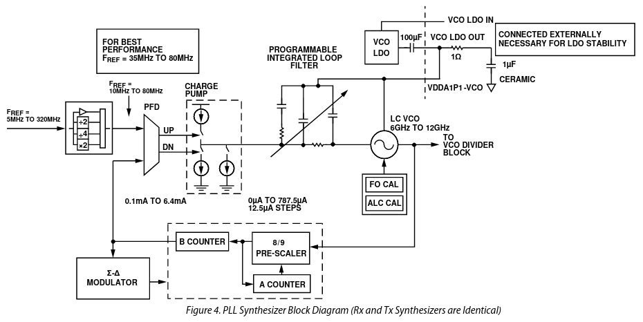
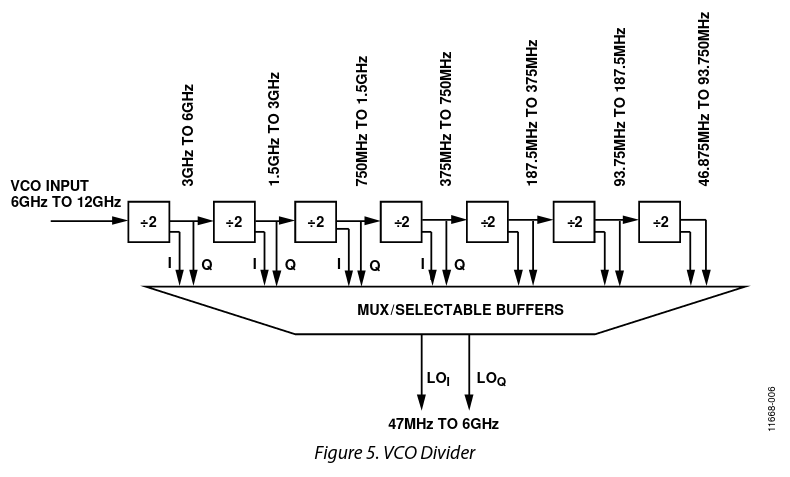
The output of the VCO is divided by a power of two according to the desired octave for the LO. The quadrature LO is obtained as part of this division.
The LO PLL fractional-N synthesis uses a denominator of 8388593, which is a prime number. The formulas are given in the figure below. Here \(F_{REF}\) already includes the prescaling.
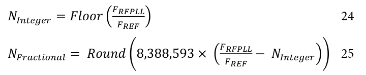
Conversely, given \(N_{Integer}\) and \(N_{Fractional}\), we have\[F_{RFPLL} = F_{REF}\cdot\left(N_{Integer} + \frac{N_{Fractional}}{8388593}\right).\]
The values of \(N_{Integer}\) and \(N_{Fractional}\) are given in registers 0x231-0x235 for the RX LO and 0x271-0x275 for the TX LO. The registers for the RX LO are shown below. The layout for the TX LO registers is analogous.

The scalers for the PLL reference are given in registers 0x2AB and 0x2AC. The same encoding as for the BBPLL reference is used (00: x1; 01: x½; 10: x¼; 11: x2).
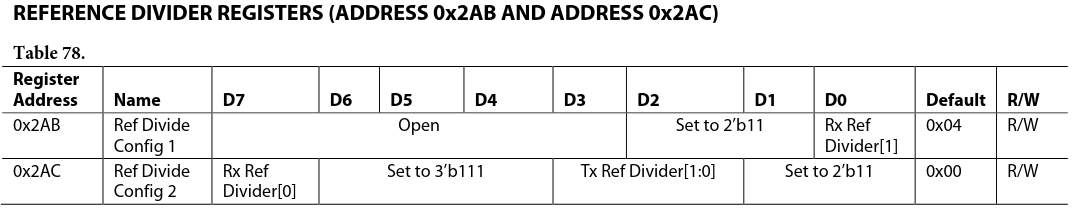
Finally, the dividers for the VCO are set in register 0x05. The possible values for these registers are shown here.
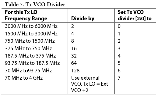
To sum up, the LO frequency can be computed as\[F_{LO} = F_{REF} \cdot R_{scale} \cdot 2^{VCODIV} \cdot \left(N_{Integer} + \frac{N_{Fractional}}{8388593}\right),\]where \(R_{scale}\) is the reference scale factor (either 1, 1/2, 1/4 or 2), \(VCODIV\) is the VCO divider setting (an integer from 1 to 7), and \(N_{Integer}\) and \(N_{Fractional}\) are the PLL control words.
Set up for the QO-100 beacons in Bochum
In view of the previous section, to compute the exact frequencies at which the beacons are transmitted by the ADALM Plutos in Bochum, it is relevant to know the following settings:
- Reference frequency
- Sample rate
- TX LO frequency
Additionally, it is also necessary to know any possible frequency synthesis errors that occur in the IQ data being sent to the Plutos (for instance, if using the GNU Radio Signal Source).
Mario and Kurt have given me the following details. First of all, both Plutos use a 40 MHz reference that is locked to Bochum’s 10 MHz GPSDO. I will assume that the synthesis of the 40 MHz reference is a simple multiplication and doesn’t have fractional-N synthesis errors. This in fact seems to be the case.
For the Pluto that generates the CW and BPSK beacons, the sample rate is set to 1 Msps, and the TX LO frequency is 2400062.5 kHz. Therefore, the CW beacons are at -62.5 and 437.5 kHz in the IQ baseband, and the BPSK beacon is at 187.5 kHz. The IQ data is generated using custom C code that Mario wrote. The carrier frequencies of the beacons are generated with table-based NCOs that use 17 bits to represent the phase. It happens that with such an NCO all the required carrier frequencies for the CW and BPSK beacons can be generated exactly. Therefore, to find the exact frequencies at which the beacons are transmitted, we only need to find the sample rate error and TX LO error.
For the Pluto that generates the 8APSK multimedia beacon, the sample rate is set to 1.8 Msps and the TX LO frequency is 2400495 kHz. Therefore, the beacon is at 0 Hz in the IQ baseband. This means that we don’t need to worry about how the carrier frequency for the generated in the IQ data (since it must be exactly zero), and also we don’t care about sample rate errors. The sample rate errors will affect the symbol rate, but not the carrier frequency, which is only determined by the TX LO frequency. For this Pluto we only need to compute the TX LO error.
Calculations for the QO-100 beacons Plutos
The easiest way to calculate the sample rate errors and TX LO errors for the Plutos is to use take a Pluto, configure it with the sample rates and TX LO frequencies given above, and then read all the registers necessary to calculate the fractional-N synthesis errors. Alternatively, it is also possible to go through the code that configures the AD9363 registers and see how it calculates their values, as I did with the LimeSDR mini. This is more time consuming and error prone. The calculations of this section are detailed in this Jupyter notebook.
The Pluto can be configured using any software, but since we will be using SSH to read the register values, it is easiest to configure it using sysfs. For instance, we can set the LO frequency in this way.
# cd /sys/bus/iio/devices/iio\:device1/
# cat name
ad9361-phy
# echo 2400062500 > out_altvoltage1_TX_LO_frequency
Unfortunately, to set the sample rate as low as 1 Msps it is necessary to configure the AD9363 FIR decimator/interpolator, which is not so easy to do with the sysfs interface. Therefore, to configure this it is easier to use another application such as GNU Radio or GQRX.
A potential pitfall is that, in addition to the AD9363 FIR, the Pluto FPGA design has a x8 decimator/interpolator FIR, so depending on how all the elements are configured, the 1 Msps rate could be achieved in different ways. Luckily, we know that the BBPLL VCO can run at a frequency between 715 and 1430 MHz, which is exactly an octave. This means that, if we don’t use the DEC3/INT3 filters (which are rarely used), the decimation/interpolation between the BBPLL and the user IQ sample rate must be a power of two, we already know which power of two we need for a given user IQ sample rate. We do not really care about how this power of two is distributed among all the decimators/interpolators.
According to the discussion above, we are certain that for a 1 Msps user IQ rate, the BBPLL should run at a frequency close to 1024 MHz. If we configure 1 Msps with GQRX using SoapySDR, we get the following rates:
# cat tx_path_rates
BBPLL:1024000000 DAC:32000000 T2:16000000 T1:8000000 TF:4000000 TXSAMP:1000000
The BBPLL register values are the following:
# iio_reg ad9361-phy 0x41
0x13
# iio_reg ad9361-phy 0x42
0x20
# iio_reg ad9361-phy 0x43
0x0
# iio_reg ad9361-phy 0x44
0x19
# iio_reg ad9361-phy 0x45
0x0
From these register values we get that the BBPLL reference scaler is 1 (leave the reference as is), \(N_{Integer} = 25\) and \(N_{Fractional} = 1253376\). With a 40 MHz reference, these give a BBPLL frequency of exactly 1024 MHz. This means that the sample rate is exactly 1 Msps as desired.
A consequence of this is that all the frequency separations between the CW and BPSK beacons match exactly the nominal ones. I think that this was not the case when the QO-100 NB transponder was inaugurated with 250 kHz of bandwidth, one CW beacon and one BPSK beacon. But it is the case now that there are two CW beacons and one BPSK beacon.
When the TX LO is set to 2400062.5 kHz as indicated above, we read the following register values.
# iio_reg ad9361-phy 0x271
0x78
# iio_reg ad9361-phy 0x272
0x0
# iio_reg ad9361-phy 0x273
0x66
# iio_reg ad9361-phy 0x274
0x66
# iio_reg ad9361-phy 0x274
0x0
# iio_reg ad9361-phy 0x275
0x0
# iio_reg ad9361-phy 0x2ac
0xff
# iio_reg ad9361-phy 0x5
0x13
These give a reference scaler of 2 (multiply by 2), a VCO output divider of 4, and \(N_{Integer} = 120\) and \(N_{Fractional} = 26214\). With these parameters, we compute an LO frequency of approximately 2400062499.158083 Hz. The frequency can also be computed exactly as a rational number. By doing so, we obtain a frequency error of -7062500/8388593 Hz, which is approximately -0.84197 Hz. This means that the TX LO, and hence the CW and BPSK beacons are all transmitted approximately -0.8 Hz below their nominal frequencies. There are no other frequency errors affecting these beacons.
For the 8APSK beacon, we can set the TX LO to 2400495 kHz and read the registers again:
# iio_reg ad9361-phy 0x271
0x78
# iio_reg ad9361-phy 0x272
0x0
# iio_reg ad9361-phy 0x273
0x2
# iio_reg ad9361-phy 0x274
0x2b
# iio_reg ad9361-phy 0x275
0x3
# iio_reg ad9361-phy 0x5
0x13
These give a reference scaler of 2 (multiply by 2), a VCO output divider of 4, and \(N_{Integer} = 120\) and \(N_{Fractional} = 207618\). The LO frequency corresponding to these parameters is approximately 2400495000.7706895 Hz. The frequency error is exactly 6465000/8388593 Hz, or approximately 0.770689 Hz. Therefore, the 8APSK beacon is approximately 0.7 Hz above its nominal frequency, as there are no other sources of error.
Putting all this together, the frequency separation of the 8APSK and BPSK beacons has an error of 13527500/8388593 Hz, which is approximately 1.612607 Hz (meaning that the frequency separation is actually 246.613 Hz).
Experimental verification
Now we can use the measurements I’ve done of the phase difference of the beacons to verify that these calculations are correct. In the previous post I was using SciPy’s detrend function to fit and remove the slope caused by the frequency separation error. Now we can stop using detrend and introduce a correction using the frequency separation error determined above. It is also necessary to include the correction for the sampling rate error of my LimeSDR mini, which I computed in the previous post (it makes the frequency separation appear 1.768 mHz larger than it is).
With these corrections, the phase difference of one of my previous measurements looks like this. Here only the average has been removed, instead of applying detrend. It is apparent that if there is a slope versus time in the data, it is very small.
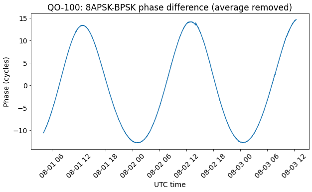
Our ability to tell if there is still a small uncorrected frequency error is limited by the perturbations of the orbit of the satellite, which have secular terms that make it change slightly every day. In fact, in the plot above it seems that the two minima have the same value, but the maxima seem to grow slightly. This could be partly caused by the secular perturbations of the orbit, and/or partly caused by a very small frequency error.
If we add an additional 20 uHz to the frequency correction, in order to simulate a small uncorrected frequency error, we get the plot below. We can see that both the maxima and the minima are decreasing, so the frequency error is visible.
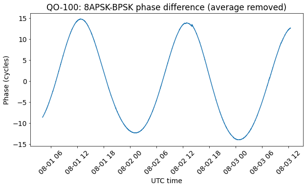
This means that our experimental data show that if there is an uncorrected frequency error in the measurement of the beacons phase difference, then it must be smaller than 20 uHz. To put things in perspective, that is a relative error of \(8.16 \cdot 10^{-11}\) with respect to the nominal separation of 245 kHz. A fractional-N divider capable of such a small change would need to have a fractional control word with a resolution of at least 33 bits. The fractional-N dividers of the AD9363 and LMS7002M are much smaller than this, as well as most other fractional-N dividers. Thus, it seems that our experimental results have enough precision to ensure that we have handled all the effects of fractional-N synthesis.
One comment