At the end of July, Benjamin Menkuec was commenting in Twitter about some issues he had while demodulating a 5G NR downlink recording. There was a lively discussion in which other people and I participated. I had never touched 5G, but had done some work with LTE, so I decided to take the chance to learn more about the 5G physical layer. Compared to LTE, the changes are more evolutionary than revolutionary, but understanding what has changed, and how and why, is part of the puzzle.
I had to take an 11.5 hour flight in a few days, so I thought it would be a nice challenge to give this a shot, take with me the recordings that Benjamin was using and all the 3GPP documents, and write a demodulator in a Jupyter notebook from scratch during the flight, as I had done in the past with my LTE recordings. This turned out to be an enjoyable and interesting experience, quite different from working at home in shorter intervals scattered over multiple days or weeks, and with internet access. At the end of the flight I had a mostly working demodulation, but it had a few weird problems that turned out to be caused by some mistakes and misconceptions. I worked on cleaning this up and solving the problems over the next few days, and also now preparing this post.
Rather than trying to give an account of all my mistakes and dead ends (I spoke a little about these in Twitter), in this post I will show the final clean solution. There are some tricky new aspects in 5G NR (phase compensation, as we will see below) which can be quite confusing, so hopefully this post will do a good job at explaining them in a simple way.
The Jupyter notebook used in this post is here, and the recording in SigMF format can be found in this folder. Here I will only be using the first of Benjamin’s two recordings, since they are quite similar. It was done with an ADALM Pluto at 7.86 Msps and has a duration of 143 ms. The transmitter is an srsRAN 5 MHz cell. The recording was done off-the-air, or maybe with a cabled set up, but there are some other signals leaking in. The SNR is very good, so this is not a problem.
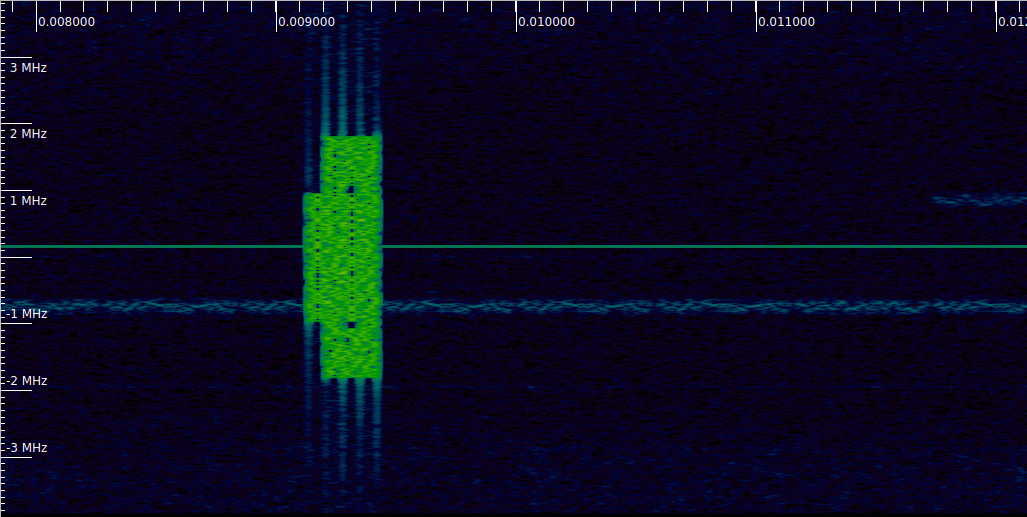
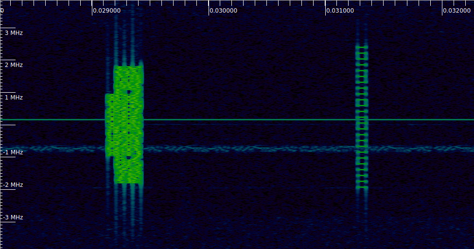
The first signal we find is at 9 ms. There is a transmission like this every 10 ms. As we will see, this is an SS/PBCH block. Something that stands out to those familiar with the LTE downlink spectrum is that the 5G NR spectrum is almost empty. In LTE, the cell-specific reference signals are transmitted all the time. In 5G this is not the case. Downlink signals are transmitted only when there is traffic. There is always a burst of one or several SS/PBCH blocks transmitted periodically (usually every 20 ms, but in this recording every 10 ms), as well as other signals that are always sent periodically (such as the SIB1 in the PDSCH), but this may be all if there is no traffic in the cell.
This post assumes some familiarity with OFDM signals and LTE. Readers unfamiliar with these might want to refer to my LTE posts, in particular to the uplink demodulation post (not because the LTE uplink has anything special to do with the 5G downlink, but rather because this was the first post in the series, so it is where some of the concepts used in later posts are introduced).
Poor man’s Schmidl & Cox
Every time we have an OFDM signal with a cyclic prefix and good SNR we can do what I call the poor man’s Schmidl & Cox. This consists in trying to correlate the cyclic prefix at the beginning of a symbol with the cyclic prefix at the end of the same symbol (they are the same waveform, so they must correlate). In contrast, the true Schmidl & Cox algorithm correlates the first half and the second half of a symbol. This gives much better SNR due to the longer correlation, but requires the signal to use only the even subcarriers, in order for the two time domain halves of the symbol to be equal. Some OFDM signals that are intended to be synchronized with this algorithm leave odd subcarriers empty on preamble symbols, but neither LTE nor 5G do this.
The poor man’s Schmidl & Cox will give us the times when the symbols start, and also a coarse frequency estimate, computed with the phase rotation over the useful symbol period. Interestingly, this algorithm works within each symbol, so it is insensitive to any special characteristics about how each symbol “connects” with the next one. The characteristics I have in mind are phase rotations between each symbol, such as the one produced by offsetting subcarriers in frequency by half the subcarrier spacing (see the “Symbol inversion” section in this post), which is something that the LTE uplink uses, and also the new phase compensation introduced in 5G (see below). When not handled properly, these features will show up as an extra, fake, carrier frequency offset when comparing the phase of the symbols as time advances. In contrast, Schmidl & Cox gives us a coarse frequency estimate that ignores these mistakes, so it can be a good “ground truth”.
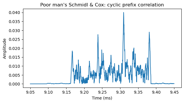
The next figure shows the correlation applied to the signal shown in the Inspectrum waterfall above. The correlation peaks correspond to the locations of the cyclic prefix at the start of each symbol. There are four symbols in this transmission, which we also could see by the keying clicks in the waterfall. The location of the first peak will be taken as the start of this transmission and used as the reference point for demodulation of the whole recording.
The next figure shows the complex values of the correlation. The frequency estimate corresponds to the angle of the correlation peaks. Here we see that the correlations peaks are mostly real and positive, so the frequency error is small. As in other posts, I have cheated, and already introduced the required carrier frequency offset, phase offset and amplitude scale in the recording, so the estimates for these errors will be small. What I have done is to apply the algorithms to the recording with no corrections, compute the corrections, and then go back and repeat everything with the corrections in place.
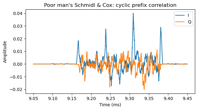
The carrier frequency offset that I’m correcting for is 18.88 Hz. Apparently the Pluto was already tuned quite accurately. After this correction, the Schmidl & Cox correlation for these four symbols shows frequency errors ranging between -6 and 42 Hz. Since this is only a rather coarse estimate, it is compatible with the carrier frequency error being close to zero.
Phase compensation
At this point we might use the symbol time offset obtained from the poor man’s Schmidl & Cox to perform OFDM demodulation of the four symbols in the SS/PBCH block. However, if we do this without taking into account 5G’s phase compensation, we will see weird frequency jumps between each symbol as time advances.
Phase compensation is a new feature of 5G NR compared to LTE, and it is also not used in other common OFDM waveforms. It is a concept that can certainly be confusing. It bit me the first time I came across it, and other people I’ve talked to also find it confusing. There are probable several different ways to understand phase compensation, but when I try to think about it in ways that should be reasonable, I end up confusing myself. Here I will try to explain it in a way that tries to motivate why it exists and tries to be the least confusing possible. Nevertheless, the section uses some OFDM math, so some people might want to skip it in a first read.
First, let’s go to the standards: 3GPP 38.211 defines the upconversion of a complex baseband 5G OFDM waveform (except for the PRACH and RIM-RS), both for the downlink and uplink, as\[\mathrm{Re}\{s_l^{(p,\mu)}(t) \cdot e^{2\pi i f_0 (t – t^{\mu}_{\mathrm{start},l} – N^{\mu}_{\mathrm{CP},l}T_c)}\}.\]As usual in 3GPP’s documentation, there are many technically correct but distracting indices and parameters. Here \(l\) indicates the time domain OFDM symbol number, and \(p\) and \(\mu\) can be safely ignored. The carrier frequency is denoted by \(f_0\), and \(t^{\mu}_{\mathrm{start},l}\) indicates the starting time of the symbol \(l\) (the starting time of its cyclic prefix). The expression \(N^{\mu}_{\mathrm{CP},l}T_c\) gives the duration of the cyclic prefix, so \(t^{\mu}_{\mathrm{start},l} + N^{\mu}_{\mathrm{CP},l}T_c\) is the starting time of the useful symbol. The complex baseband OFDM waveform \(s_l^{(p,\mu)}(t)\) is defined in the usual way (again with many unimportant variables) as\[s_l^{(p,\mu)}(t) = \sum_{k=0}^{N_{\mathrm{grid},x}^{\mathrm{size},\mu} N_{\mathrm{sc}}^{\mathrm{RB}}} a_{k,l}^{(p,\mu)} e^{2\pi i (k + k_0^\mu – N_{\mathrm{grid},x}^{\mathrm{size},\mu} N_{\mathrm{sc}}^{\mathrm{RB}}/2) \Delta f (t – N^{\mu}_{\mathrm{CP},l}T_c – t^{\mu}_{\mathrm{start},l})},\] for \(t^{\mu}_{\mathrm{start},l} \leq t \leq t^{\mu}_{\mathrm{start},l} + T^{\mu}_{\mathrm{symb},l}\), where \(T^{\mu}_{\mathrm{symb},l}\) is the total duration of the symbol \(l\), including cyclic prefix. Here \(\Delta f\) denotes the subcarrier spacing. This is just your usual OFDM expression, even though it might not be immediately obvious because of the somewhat confusing notation.
What is different from how other OFDM waveforms work is the presence of the term \(t^{\mu}_{\mathrm{start},l} + N^{\mu}_{\mathrm{CP},l}T_c\) in the upconversion. Other OFDM waveforms including LTE do the upconversion as\[\mathrm{Re}\{s_l^{(p,\mu)}(t) \cdot e^{2\pi i f_0 t}\}.\]This is not given as a formula, but rather as a diagram in Sections 5.8 and 6.13 in 36.211, but this is the formula you get from the diagram.
LTE and other OFDM waveforms do the upconversion using a phase continuous local oscillator \(e^{2\pi i f_0 t}\). This makes perfect sense, because in the real world local oscillators are phase continuous. In contrast, 5G NR includes the extra term \(e^{-2\pi i f_0 (t^{\mu}_{\mathrm{start},l} + N^{\mu}_{\mathrm{CP},l}T_c)}\), which is different for each symbol \(l\) and in general causes phase discontinuities in the local oscillator at the boundaries of each symbol, because the carrier frequency \(f_0\) multiplied by the total symbol duration is not an integer (in practice transmitters don’t implement this by applying phase discontinuities to the local oscillator, but rather by applying the equivalent phase rotations in complex baseband).
Let’s back off for a moment from these formulas and try to motivate where the extra term in 5G NR may come from. For this, we consider a generic OFDM waveform with a cyclic prefix length that can vary on each symbol. We have in mind the particular case of LTE and 5G, which in their most common configuration both have a subcarrier spacing of 15 kHz and 7 symbols in each 0.5 ms period, of which the first one has a slightly longer cyclic prefix than the remaining ones. Using a notation inspired by the one in 38.211, but somewhat simplified, we define our complex baseband OFDM symbol by\[s_l(t) = \sum_{k=-N/2}^{N/2-1} a_{k,l} e^{2\pi i k \Delta f (t – t_{\mathrm{start},l} – T_{\mathrm{CP},l})}.\]Here \(N\) denotes the IFFT size (which we assume to be even), so some of the \(a_{k,l}\) will typically be zero. The duration of the cyclic prefix for symbol \(l\) is denoted by \(T_{\mathrm{CP},l}\). We assume that this complex baseband waveform is upconverted in the usual phase-continuous way, although we can equivalently work in complex baseband all the time for this reasoning.
In this OFDM waveform there is a subcarrier which is the DC subcarrier, corresponding to \(k = 0\). Now we ask ourselves what happens if a receiver wants to renumber the subcarriers and treat as the DC subcarrier another subcarrier \(k_0\). By this, we mean performing a frequency translation \(s_l(t) e^{-2\pi i k_0 t}\) so that the subcarrier \(k_0\) ends up as the DC subcarrier in the OFDM demodulation FFT. At first, this might seem just a simple renumbering of indices, and also somewhat unjustified, but it is neither. Let us first justify why a receiver may want to do this.
Suppose that a receiver is only interested on a contiguous subset of subcarriers of the full OFDM signal, and that this subset is not symmetric about the DC subcarrier. The receiver might want to treat as DC subcarrier the centre of this subset. There are two main reasons for this. The first is computational. By doing this, the receiver can compute a smaller FFT that encompasses only the subcarriers of interest. Doing this requires renumbering the subcarriers, because in general we do not want the original DC subcarrier to be at the centre of our smaller FFT.
The second reason is more profound. If we try to estimate carrier phase offset and symbol time offset in a set of subcarriers that is skewed with respect to the DC subcarrier, we will find that we can mistake a carrier phase offset for a symbol time offset and vice versa. The reason is simply that the carrier phase offset and symbol time offset are given, respectively, by the independent term and the leading term of a degree one polynomial (a straight line) that fits the phase versus subcarrier measurements. If the subcarriers in which we measure are skewed with respect to zero (the DC subcarrier), then the estimates for the two coefficients of this polynomial are no longer uncorrelated. Renumbering subcarriers to treat the centre of the set of subcarriers being used as DC fixes this problem.
While this operation might seem as a simple renumbering of subcarriers, the following thought experiment shows that there is something fundamental about the DC subcarrier, so we cannot simply treat any other subcarrier as the DC subcarrier without making adjustments. Consider that only the DC subcarrier is used (the remaining \(a_{k,l}\) are set to zero), and that the same symbol is transmitted all the time (for example, set \(a_{0,l} = 1\) for all \(l\)). Then the OFDM waveform that we get is a phase-continuous CW tone. This is true both at complex baseband and when the waveform is upconverted to RF. If we now try to do the same for a different subcarrier \(k \neq 0\), we find that what we get has phase jumps at the boundaries of each symbol because of the presence of the cyclic prefix (the waveform would also be a phase-continuous CW tone if there was no cyclic prefix). This shows that the DC subcarrier is special. If we are given an OFDM RF waveform, we can identify which subcarrier was used as DC subcarrier during the OFDM modulation, even if this was not in the middle of the set of active subcarriers.
If we now work out the math, we see that using the substitutions \(r = k – k_0\) and \(b_{r,l} = a_{r+k_0,l}\), we can write the frequency shifted OFDM symbol as\[s_l(t) e^{-2\pi i \Delta f k_0 t} = e^{-2\pi i \Delta f k_0(t_{\mathrm{start},l} + T_{\mathrm{CP},l})} \sum_{r = -N/2-k_0}^{N/2 – 1 – k_0} b_{r,l}e^{2\pi i r \Delta f(t – t_{\mathrm{start},l} – T_{\mathrm{CP},l})}.\]The summation is just a regular OFDM symbol where the subcarriers have been renumbered so that \(k_0\) is the DC subcarrier. The summation indices are not symmetric about \(r = 0\), but this is unimportant because probably we are only going to process a smaller subset of subcarriers. We can denote this OFDM symbol by \(\widetilde{s}_l(t)\). However, in addition to this symbol, we see that we get the factor \(e^{-2\pi i \Delta f k_0(t_{\mathrm{start},l} + T_{\mathrm{CP},l})}\). This depends on the symbol index \(l\), but since we know all the terms involved, we can have our receiver process the OFDM waveform as if the subcarrier \(k_0\) was DC, and then cancel out this extra factor by applying a phase correction that depends on \(l\).
In practical situations the phase correction is quite manageable. If there is an integer \(L\) such that the duration of \(L\) consecutive symbols multiplied by \(\Delta f k_0\) is an integer, then we see that the phase correction depends only on \(l\) modulo \(L\). For the usual 15 kHz subcarrier spacing of LTE and 5G, we can always take \(L = 14\), and also \(L = 7\) if \(k_0\) is even. The phase corrections can even be precomputed as a table of length \(L\), and the correct term can be applied by knowing the symbol index within the group of \(L\) consecutive symbols.
However, something very important in all of this is that so far we have assumed that the receiver knows the index \(k_0\), or equivalently, that it knows what is the subcarrier that the transmitter used as DC. Imagine an OFDM waveform that potentially has a large number of subcarriers, but usually only a small portion of them (not centred about the DC subcarrier) are in use. A receiver might detect the presence of the waveform because of the subcarriers that are active. However, it might not know the relative position that these subcarriers occupy in the frequency grid of the full OFDM waveform. In other words, it might not know the indices \(k\) of the subcarriers that it has detected. In this case, it cannot apply the phase correction and operate with the set of active subcarriers by treating one of them as DC. I don’t know much about the system levels requirements of 5G, but I think that this situation is considered as a use case.
The phase compensation of 5G solves this problem. If instead of upconverting our complex baseband OFDM waveform as \(\mathrm{Re}\{s_n(t) e^{2\pi f_0 t}\}\) we upconvert it as \(\mathrm{Re}\{s_n(t) e^{2\pi f_0 (t – t_{\mathrm{start},l} – T_{\mathrm{CP},l})}\}\), we can repeat the same kind of calculation and see that when the receiver downconverts this RF waveform by multiplying by \(e^{-2\pi i (f_0 + \Delta f k_0) t}\), the complex baseband waveform that it will obtain is\[e^{-2\pi (f_0 + \Delta f k_0) ( t_{\mathrm{start},l} + T_{\mathrm{CP},l})} \widetilde{s}_l(t).\]Now the phase correction term that it needs to apply depends on \(f_0 + \Delta f k_0\), and this is an absolute RF frequency. It is no longer relative to the subcarrier that was used as DC in the transmitter. It is the nominal RF frequency of the subcarrier that the receiver wants to use as DC. As long as the receiver carrier frequency offset is not too large, it can identify the nominal carrier frequencies of the active subcarriers that it has detected.
There are a couple of additional remarks that help motivate exactly why these particular phase jumps are used in the 5G phase compensation, besides the reason “so that the math works out in the receiver”. The first is that all the subcarriers of a complex baseband OFDM waveform have their phase aligned at zero at the start of the useful symbol (just think of the definition). The 5G phase compensation term is the required expression so that this property is also true for the subcarriers in the upconverted waveform. The second remark is that the 5G OFDM waveform can actually be seen (at least in the case in which \(f_0\) is an integer multiple of \(\Delta f\)) as an OFDM waveform whose DC subcarrier is actually at RF DC, and the set of used subcarriers is way up in the RF range around the intended carrier frequency. In this sense, none of the active subcarriers is special (none are the DC subcarrier), and a receiver can identify the subcarrier index \(k\) of each of them by measuring their RF frequency.
In practice, to handle the phase compensation for the recording used in this post, we need to know that the subcarrier that is close to 0Hz in the recording (which we will use as DC) has a nominal frequency \(f_{\mathrm{DC}}\) of 1876.95 MHz. Once we know this, and taking advantage that this carrier frequency is a multiple of 2 kHz, we can build a table of \(L = 7\) phase corrections, and apply them depending on the symbol index modulo 7. Our table of phase corrections can have a constant phase error, since this will be absorbed by the receiver phase error. Therefore, we simply build the table as \(e^{2\pi i f_{\mathrm{DC}} T_{\mathrm{CP},1} l}\), for \(l = 0, 1, \ldots, 6\). Here \(T_{\mathrm{CP},1}\) denotes the duration of the cyclic prefix of all symbols except the first in each group of 7 (which has a slighly longer cyclic prefix).
The SS/PBCH block
Now that we know about the 5G NR phase compensation, we can demodulate the four symbols in the transmission that we are analysing, which is an SS/PBCH block. The SS/PBCH block is the replacement in 5G for the LTE PSS (primary synchronization signal), SSS (secondary synchronization signal) and PBCH (physical broadcast channel). The SS/PBCH block also contains the PSS, SSS, and PBCH, but each of these is somewhat different from their LTE counterparts.
The following diagram shows the time-frequency structure of the SS/PBCH block. Note that this looks just like what we saw in Inspectrum. The block is composed by four consecutive OFDM symbols. The starting symbol of the block is either symbol 2 or symbol 8 (using zero-based numbering) in a 1 ms subframe, so none of the symbols have the slightly longer cyclic prefix of symbols 0 and 7. In contrast with LTE, the SS/PBCH block can be transmitted anywhere in the cell frequency grid. It does not need to be centered about the DC subcarrier.
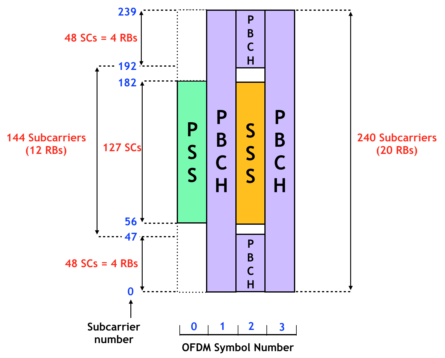
The PSS and SSS are BPSK modulated using pseudorandom sequences that depend on the cell ID. This contrasts with LTE, where the PSS is a Zadoff-Chu sequence. The 5G cell ID is defined as in LTE, as \(N_{\mathrm{ID}}^{\mathrm{cell}} = 3 N_{\mathrm{ID}}^{(1)} + N_{\mathrm{ID}}^{(2)}\), although the range of possible values for \(N_{\mathrm{ID}}^{(1)}\) is from 0 to 335 (in LTE it was from 0 to 167). The possible values of \(N_{\mathrm{ID}}^{(2)}\) are still 0, 1, and 2. As in LTE, the PSS only depends on \(N_{\mathrm{ID}}^{(2)}\), so there are only 3 possible waveforms to search for cell discovery, and then once \(N_{\mathrm{ID}}^{(2)}\) is know, we can find \(N_{\mathrm{ID}}^{(1)}\) from the SSS. The pseudorandom sequences used for the construction of the PSS and SSS are based on m-sequences of length 127, so this explains why they use 127 subcarriers.
As shown in the figure above, the PBCH is transmitted around the SSS. This is different from LTE, where the signals were transmitted sequentially in time (first SSS, then PSS, then four PBCH symbols). The PBCH has its own DM-RS (demodulation reference signal), because there are no cell-specific reference signals active all the time as in LTE. The PBCH DM-RS occupies the subcarriers whose index is congruent with the cell ID modulo 4.
PSS
To demodulate the PSS, and the other signals in the SS/PBCH block, we need to know the subcarrier index at which the SS/PBCH block starts. In our case we can do this easily by looking at which subcarriers are active. The following figure shows the power of all the subcarriers after OFDM demodulation of the PSS. Using this we find that the SS/PBCH block starts at subcarrier -120 with respect to the subcarrier that we have chosen to use a DC subcarrier.
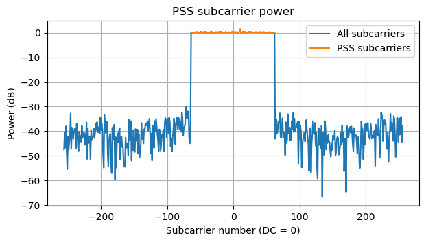
Here is the constellation of the PSS. Everything looks good, because as I have mentioned, I’m cheating and have already applied the carrier frequency, phase and amplitude corrections required.
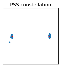
The three possible PSS sequences (depending on \(N_{\mathrm{ID}}^{(2)}\)) are circular shifts of a 127-bit m-sequence. In our case we can simply find that \(N_{\mathrm{ID}}^{(2)} = 1\) by trial and error. After wiping off the sequence, we obtain the following constellation. Here the symbol time offset comes from the poor man’s Schmidl & Cox, and it has a resolution of one sample, so there is a little of sub-sample symbol time offset. This will be corrected later. Also, we see that one of the subcarriers is somewhat off. This is caused by a CW interference, which can be seen in the waterfall or in the spectrum above.
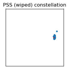
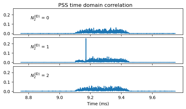
This is usually not how a receiver uses the PSS, because here we have started with a rather good symbol time offset by using the poor man’s Schmidl & Cox. Usually, a time domain correlation is done with the three possible PSS symbols to find the location of the start of the PSS (which gives us the symbol time alignment) and the \(N_{\mathrm{ID}}^{(2)} = 1\). In doing this, the correct frequency offset needs to be used when generating the time-domain PSS waveform. The results of doing this are shown in the next plot.
SSS
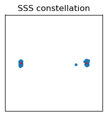
We can obtain the SSS by demodulating two symbols after the PSS. Here it is important to use the 5G phase compensation correction correctly, or we would get a weird phase jump between the PSS and SSS that might lead us to think that there is a carrier frequency offset. The constellation is shown here.
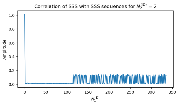
The SSS sequence depends both on \(N_{\mathrm{ID}}^{(2)}\), which we already know, and on \(N_{\mathrm{ID}}^{(1)}\), which we don’t. There are two possible ways to find the correct SSS sequence, and with it, the value of \(N_{\mathrm{ID}}^{(1)}\). The first is brute force correlation against the sequences for all the possible values of \(N_{\mathrm{ID}}^{(1)}\). The result is shown here. We see that \(N_{\mathrm{ID}}^{(1)} = 0\), so the cell ID is 1.
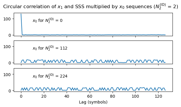
As in the case of LTE, there is a cleverer more efficient way that exploits the construction of the SSS sequence. The SSS sequence is a Gold-code-like signal that is constructed from two 127-bit m-sequences \(x_0\) and \(x_1\). The SSS sequence is the XOR of \(x_0\) circularly shifted by \(m_0\) positions and \(x_1\) circularly shifted by \(m_1\) positions. While \(m_1 = N_{\mathrm{ID}}^{(1)} \mod 112\), the good thing is that\[m_0 = 15 \left\lfloor\frac{N_{\mathrm{ID}}^{(1)}}{112} \right\rfloor + 5N_{\mathrm{ID}}^{(2)}.\]Since we know \(N_{\mathrm{ID}}^{(2)}\), there are only 3 possibilities for \(m_0\).
What we can do is, for each possibility of \(m_0\), XOR the received SSS with \(x_0\) shifted by \(m_0\), so that only the contribution of \(x_1\) remains, and then perform a circular correlation between this and \(x_1\) to obtain \(m_1\). The circular correlation can be done efficiently with FFTs (though such an FFT is tricky to implement, because 127 is prime). From the values of \(m_0\) and \(m_1\) we can recover \(N_{\mathrm{ID}}^{(1)}\). The result of this approach is shown here.
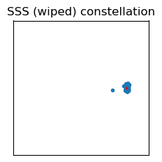
After wiping off the SSS sequence, we obtain the following constellation.
OFDM demodulation
At this point I have performed the OFDM demodulation of all the symbols in the recording. In this demodulation I am also taking into account a sampling frequency offset and fine symbol time offset (which will be estimated below). The time offset for each symbol is decomposed as an integer number of samples, which can be applied by choosing the starting sample for OFDM demodulation, and a sub-sample delay, which is applied as a phase slope in the frequency domain after OFDM demodulation.
Additionally, here and in the previous OFDM demodulations I am starting the demodulation at the middle of the cyclic prefix rather than at the beginning of the useful symbol for maximum robustness against symbol time offset errors. This also needs to be compensated as a phase versus frequency slope after demodulation.
To demodulate all the OFDM symbols properly, it is important to know which is the first symbol in each 0.5 ms half-subframe, because it has a slightly longer cyclic prefix, and because the phase compensation correction resets at these symbols. Since in the recording we are using there is a single SS/PBCH block per 10 ms radio frame, we know that this block starts at symbol 2 of the first subframe of each radio frame.
PBCH
As mentioned above, the PBCH occupies three symbols in the SS/PBCH block (one of these symbols is shared with the SSS), and one out of every four subcarriers is used as DM-RS. Both the PBCH data and its DM-RS are QPSK modulated. The DM-RS sequence is generated with the generic pseudorandom sequence algorithm, which is the same as in LTE, a \(2^{31}-1\) bit Gold code (using a 31-bit register). The initial value for the Gold code is\[c_{\mathrm{init}} = 2^{11}(\overline{i}_{\mathrm{SSB}}+1)(\lfloor N_{\mathrm{ID}}^{\mathrm{cell}} / 4 \rfloor + 1) + 2^6 (\overline{i}_{\mathrm{SSB}}+1)(N_{\mathrm{ID}}^{\mathrm{cell}} \mod 4).\]Here \(\overline{i}_{\mathrm{SSB}}\) essentially is the index of the SS/PBCH block in a 10 ms radio frame (it counts repetitions of the SS/PBCH block in the same radio frame). Using a different DM-RS for each repetition of the SS/PBCH block allows the receiver to identify which repetition it is processing, by blind searching the DM-RS, and so to obtain time synchronization to the radio frame. In this recording there is only one SS/PBCH block per radio frame, so \(\overline{i}_{\mathrm{SSB}}\) is always zero.
With this knowledge we can demodulate the PBCH and wipe-off the sequence for the DM-RS. The following figure shows the constellations of the three signals in each SS/PBCH block in the recording (there are 13 of them, the first one appearing at ~9 ms, and the last one at ~139 ms). Each SS/PBCH block corresponds to a row in the figure. The PSS and SSS are shown with the sequences wiped off in the first and second columns respectively. The PBCH and its DM-RS are shown in the third column. The data symbols are plotted in blue, and the wiped-off DM-RS symbols are plotted in green.
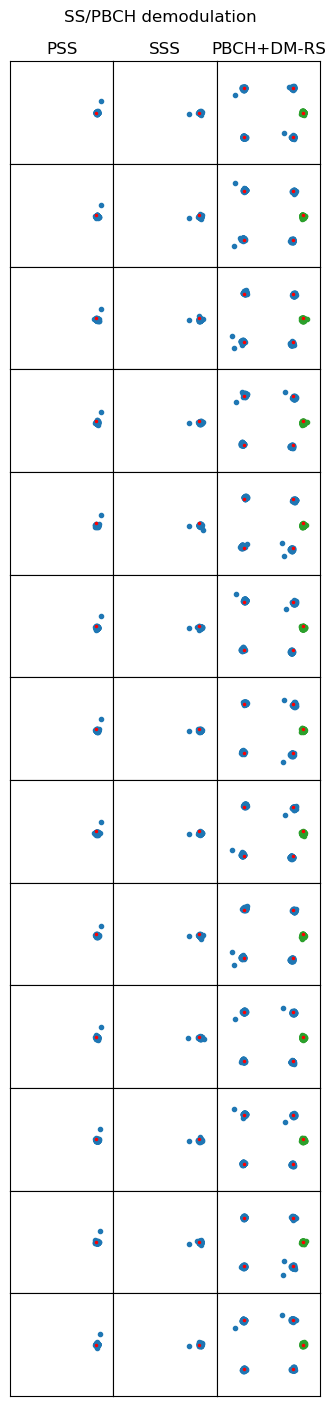
Since I have adjusted the carrier frequency offset, phase offset, amplitude, sampling frequency offset and symbol time offset, the OFDM demodulation stays well synchronized throughout all the recording.
Symbol time offset
To adjust the initial symbol time offset more finely than what obtained with the poor man’s Schmidl & Cox, and to determine the sampling frequency offset, I have used the demodulated PSS to measure the phase versus frequency slope by fitting a polynomial of degree one to the phase of the wiped-off PSS subcarriers. The resulting symbol time offset is shown here.
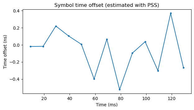
This plot has been obtained already correcting for initial symbol time offset and sampling frequency offset, so the resulting time offset is close to zero. To obtain these parameters, a polynomial of degree one is fitted to this plot. The independent term gives the initial symbol time offset, and the leading coefficient gives the sampling frequency offset, which is -3.2 ppm for this recording.
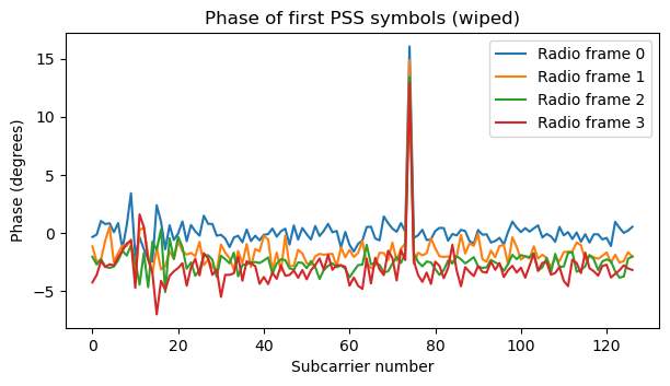
Additionally, to check the channel response, I have plotted the phase of the subcarriers of the first four PSS symbols. The phase is quite flat, as should be the case with a channel without multipath or dispersive effects (the spike is caused by the CW interference).
Other signals in the recording
Finally, I have turned my attention to the rest of the signals in the recording. Since there are not many, I can go manually over each of them. To locate the signals quickly, I have plotted the total signal power in each symbol, classified by radio frame. Each row of the plot corresponds to a radio frame. Symbols in the radio frame follow the unconventional approach of starting at the PSS, since this is the first symbol I have demodulated. The PSS should be symbol number 2 (with zero-based indexing) in the frame. This difference is not very important, specially because there are never any signals in symbols 0 and 1 in this recording.
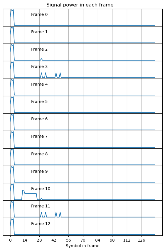
We see that the SS/PBCH block appears in the same position in each radio frame. It is also interesting to see the variations in signal power of the four symbols in the SS/PBCH block. These are caused because a different number of subcarriers are in use in each symbol (since each subcarrier has always the same power, the total power we see is proportional to the number of active subcarriers).
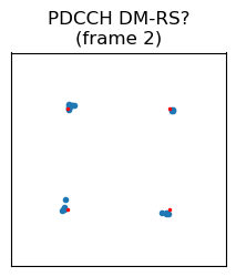
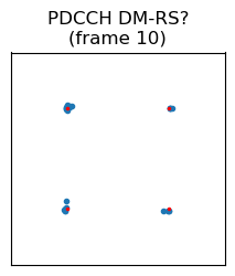
Most radio frames only contain the SS/PBCH block, but a few frames contain other signals. Frame number 2 contains a signal that occupies a single symbol. It appears in symbol 32 in the radio frame (properly counting the PSS as symbol 2), which is symbol 4 in subframe 2. Looking at the waterfall, we see that the subcarriers are sparsely used. In fact, only one in every 12 subcarriers is active. The same kind of signal appears in the same position in frame number 10.
I haven’t tried too hard to identify each of the signals in this section, since I’m not yet too familiar with the whole zoo of 5G NR signals. The 3GPP documents are not the best to identify them, since it’s easy to get lost in the notation. A book or webpage with some diagrams and examples is a much better resource.
In this case, while analysing the recording during my flight, I noted down that these are maybe the PDCCH DM-RS signals, since 38.211 Section 7.4.1.3.2 says that they use one subcarrier in each resource block (i.e., every 12 subcarriers). However, in hindsight this is somewhat strange, because there are no accompanying PDCCH data symbols. Maybe the PDCCH can just be empty, but its DM-RS needs to be present. Or perhaps this is some kind of “channel sounding” reference signal (such as the CSI RS). It will be good to come back to these signals in a future post and identify them properly. The constellation plots of these two signals are shown here. They are QPSK modulated.
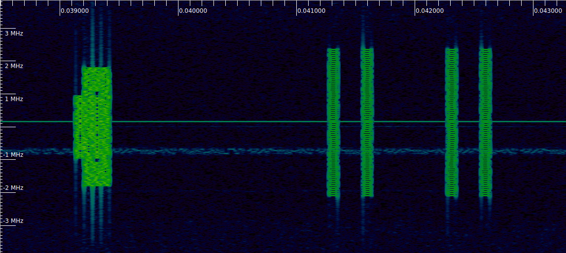
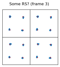
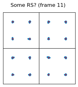
In frame 3 there are signals that use four OFDM symbols. They appear in symbols 32, 36, 46, and 50 in the radio frame, which are symbols 4 and 8 in subframes 2 and 3. They use one out of every four subcarriers.
The constellation plots for these signals are shown here. Each OFDM symbol is shown in a different square in the 2×2 grid. In my flight I took note that maybe these are some kind of reference signal, since they use the subcarriers sparsely.
Radio frame 10 is the busiest. Besides the same signal as in frame 2, we see a few other signals.
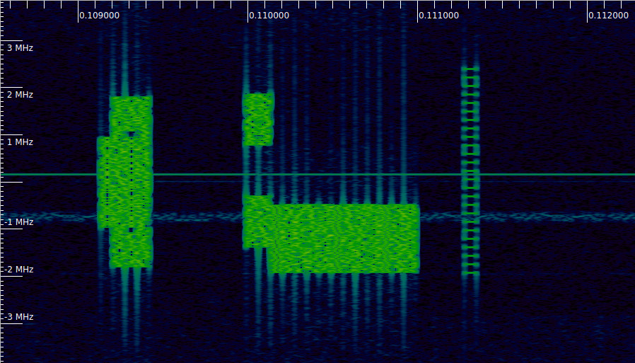
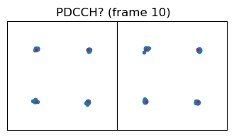
The first of these signals occupies two symbols in the time domain, and two segments of 6 resource blocks with a gap of 6 resource blocks in the frequency domain. The symbols used by these signal are 14 and 15, which are the first and second symbol in subframe 2. During my flight I took note that maybe this is the PDCCH, though I’m not sure about this. Note that if this is in fact the PDCCH, then it doesn’t make much sense for the sparse refrence signal to be the PDCCH DM-RS, because it is quite far apart in time.
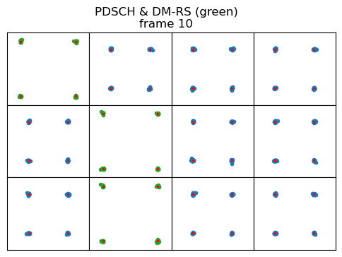
The next signal occupies 8 resource blocks in the frequency domain, and 12 symbols in the time domain (symbols 2 to 13 in subframe 2). The signal in symbols 2, 7, and 11 is different. It only uses every other subcarrier and its amplitude is \(\sqrt{2}\) instead of one. I think this is the PDSCH, and the special symbols are its DM-RS. I have marked them as such in the figure below. All the symbols are QPSK modulated.
There are no more signals in the recording. Probably at this point I have some people yelling at me that I have misidentified some of these signals, but this seems a good way of finding out what they actually are. In any case, eventually I’ll read more about 5G and come back and do a proper classification.
4 comments