Last summer I looked at the demodulation of the 5G NR downlink, using a short recording of an idle srsRAN gNB made by Benjamin Menkuec. In that post I looked at the phase compensation, which is new in NR compared to LTE, the SS/PBCH block, and performed OFDM demodulation of all the signals in the recording. One of these signals was the PDSCH transmitting the SIB1 (which is done periodically even on an idle cell), and its corresponding PDCCH transmission. However, there were some reference signals that I wasn’t able to identify at the time. In this post I will look at these reference signals in detail, and also to the DM-RS (demodulation reference signal) in the PDCCH and PDSCH.
Signals in the recording
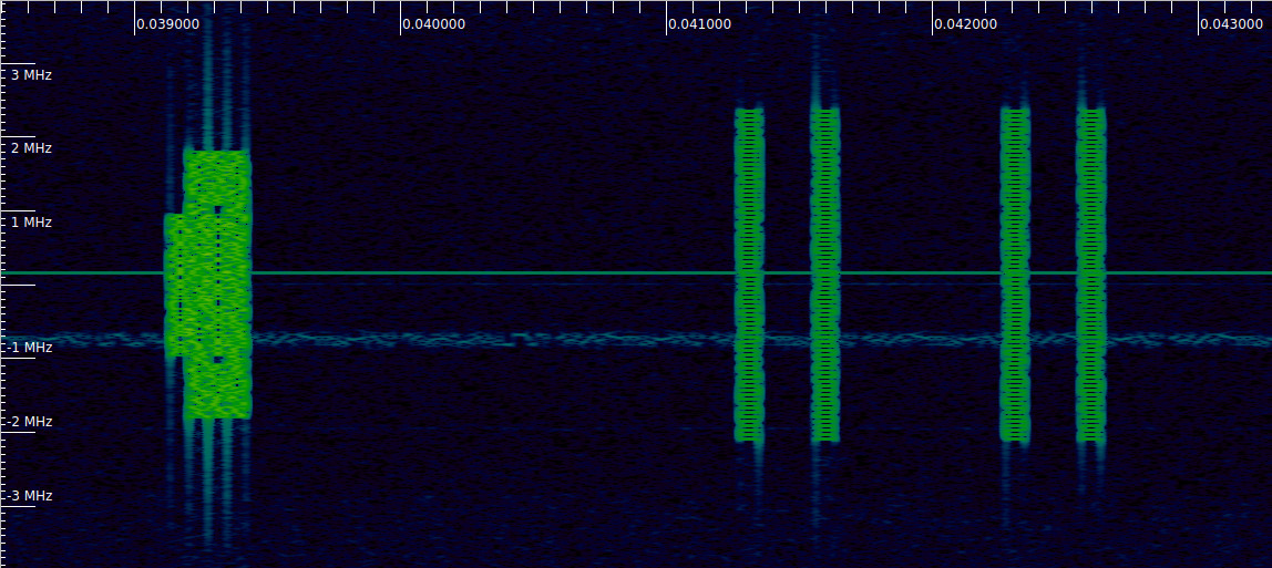
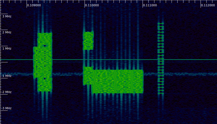
Let’s begin by recalling the signals that are present in the recording. The recording is a short IQ recording of a 5 MHz cell done at 7.68 Msps, and the SNR is very good. The following plot shows the signal power in each OFDM symbol in each frame. This follows the unconventional approach of numbering as symbol 0 the symbol where the SS/PBCH block begins. In reality, the SS/PBCH in this recording begins in symbol 2 of each radio frame, so take this into account when interpreting the plot.
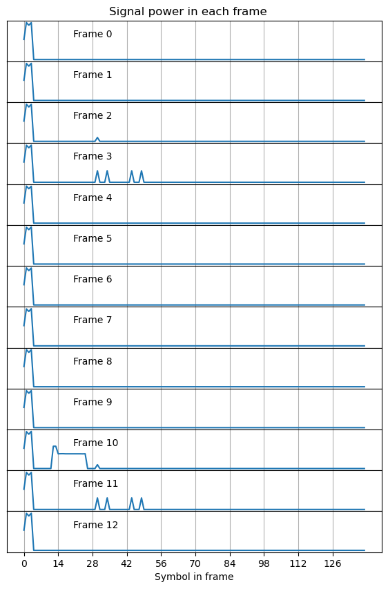
The reference signals occur in frames 2 and 10, and frames 3 and 11. They seem to be transmitted with a periodicity of 8 frames, or 80 ms. Reference signals in NR are highly configurable. The higher layers can announce to the UEs what kinds of reference signals are available. However, we can also figure out these details by doing signal analysis. These reference signals are needed in NR because it doesn’t have the CRS (cell-specific reference signal) of LTE.
Technically, the two different reference signals that are present in this recording are both CSI-RS (channel state information reference signal). Thus, the signals are constructed in the same way, as indicated by Section 7.4.1.5 in TS 38.211. However, they are configured in a different way, as they are intended to be used for different purposes. The srsRAN source code where these signals are configured is available, and this helps to understand the role played by each reference signal.
CSI-RS
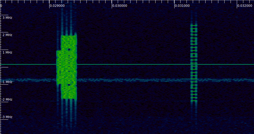
The first signal we look at is the CSI-RS, which is shown in the right hand side of this waterfall. It is clear that the subcarriers are used sparsely. In fact, only one out of every 12 subcarriers is active.
The way to find if we have correctly understood how a reference signal is generated is to generate the pseudorandom sequence that is used to modulate the reference signal. By multiplying the received signal with the complex conjugate of the correct pseudorandom sequence, we obtain a pure pilot signal. If we have made a mistake, we obtain something else. This process is known as wiping off the pseudorandom sequence.
The following plots show the wiped-off symbols for the CSI-RS’s of frames 2 and 10, together with the parameters used to construct the signal (which are the same in both cases). Some of these parameters affect the initialization value for the pseudorandom sequence, and others affect the mapping to physical resources.
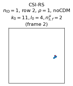
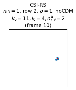
The \(n_{\text{ID}}\) parameter is used in the generation of the initialization value for the pseudorandom sequence. This is the only of these parameters that is a priory unknown for us, because the other parameters describe the symbol within the radio frame in which the CSI-RS is transmitted. According to TS 38.211, “\(n_{\text{ID}}\) equals the higher-layer parameter scramblingID or sequenceGenerationConfig.” We don’t have access to this higher-layer information, but by some trial and error I’ve found that \(n_{\text{ID}} = 1\) in this recording. This is a good guess because the physical cell ID is also 1, and in the generation of other similar pseudorandom sequences, the physical cell ID plays the same role that \(n_{\text{ID}}\) plays here.
The mapping to physical resources of a CSI-RS is mainly defined in terms of Table 7.4.1.5.3-1, which lists all the possible patterns in the time-frequency grid that a CSI-RS can have. In this case, the configuration in row 2 is used. This is the simplest configuration: it only uses a single symbol and one out of every 12 subcarriers (one subcarrier per resource block). The density \(\rho\), and the CDM type are given by the table row. Additionally, the CSI-RS takes an offset \((k_0, l_0)\) in the time-frequency grid. Here \(k_0 = 11\), which means that the uppermost subcarrier of each resource block is used, and \(l_0 = 4\), which means that the signal appears in symbol 4 in the subframe. Additionally, \(n_{s,f}^\mu = 2\), meaning that the signal appears in subframe 2 in the radio frame.
We can see the code that configures this CSI-RS signal is the make_channel_measurement_nzp_csi_rs_resource function in srsRAN. The configuration in this function matches what we have found (this cell has only one port).
This CSI-RS is intended for channel measurement by the UE, so in a sense it is the “main” CSI-RS. The signal allows a UE to estimate the downlink channel. It is transmitted only every 80 ms because it is assumed that the channel doesn’t change significantly over timescales shorter than this. It only uses one in every 12 subcarriers because it is assumed that the channel response for subcarriers that are nearer than this is highly correlated (this is related to the delay spread of the channel). In this way, the CSI-RS spends only a very small amount of downlink resources compared to the LTE CRS.
TRS
The second reference signal that appears in the recording is the TRS (tracking reference signal). This is a CSI-RS that is specifically configured to measure the channel coherence over time (to estimate Doppler spread, for instance). Here is a paper that talks about this. The TRS appears in two consecutive subframes, and in each of the subframes it appears in two symbols that are 4 symbols apart. Therefore, it allows the UE to measure the channel correlation over delays of 4 symbols and 1 subframe (1 ms). We can also see in the waterfall that the TRS is more dense than the main CSI-RS: it uses one out of every 4 subcarriers, instead of 1 out of every 12.
The following plots show the wiped-off symbols for the TRS in frames 3 and 11. Since the TRS is a CSI-RS, the parameters that control its configuration are the same as for the main CSI-RS, but have different values.
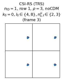
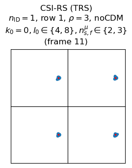
The TRS uses row 1 in the table, which corresponds to using subcarriers \(k_0, k_0 + 4, k_0 + 8\) in each resource block in order to occupy one out of every 4 subcarriers. For this signal, \(k_0 = 0\), so the subcarriers that are used in each resource block are 0, 4 and 8. The TRS appears at symbols \(l_0 = 4, 8\). The first symbol is the same symbol as the one in which the main CSI-RS appeared, but there is a second symbol three symbols later. As mentioned above, the TRS appears in two adjacent subframes: 2 and 3.
The srsRAN source code configures the TRS in the fill_tracking_nzp_csi_rs_resource function. The configuration in the code matches what we have found. Something I haven’t understood well is why there is a CSI-RS for channel estimation, and then a TRS, since the UE could also use the TRS for channel estimation. It seems that the srsRAN source code gives a clue, because it always configures the TRS for one antenna port. Maybe this is the main point of the main CSI-RS: it is transmitted over as many ports as the gNB has (srsRAN only considers 1, 2, and 4 ports, but the table in TS 38.211 covers up to 32 ports). This allows the UE to estimate the channel for each port. Therefore, the main CSI-RS must be quite efficient in terms of resource element utilization if there are many ports, and this is where complicated CDM schemes come into play. On the other hand, the TRS is used by the UE to estimate Doppler spread and similar channel statistics, so it can be transmitted over just one of the gNB ports under the assumption that these statistics will be similar for all the ports.
PDSCH DM-RS
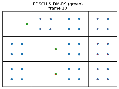
Frame 10 in the recording has a PDSCH transmission. This actually corresponds to the SIB1, which is always transmitted periodically. Since in NR there is no CRS, each downlink channel has its own DM-RS (demodulation reference signal). In the previous post we already saw how the DM-RS of the PBCH looks like, and I already indicated that the PDSCH DM-RS occuppies symbols 0, 5, 9 in the PDSCH transmission (counting as symbol 0 the first symbol of the PDSCH transmission), while symbols 1, 2, 3, 4, 6, 7, 8, 10, and 11 are used to transmit the data. The PDSCH DM-RS only uses every other subcarrier, and its constellation has amplitude \(\sqrt{2}\) rather than one so that it has the same power as the data symbols. However, in the previous post I didn’t generate and wipe-off the pseudorandom sequence.
The initialization value for the pseudorandom sequence used in the PDSCH DM-RS is given in Section 7.4.1.1.1 in TS 38.211. The formula depends on several variables whose value depends on higher-layer configuration. However, in this case, they have simple values. The variables \(\overline{\lambda}\) and \(\overline{n}_{\text{SCID}}^{\overline{\lambda}}\) are zero, and \(N_{\text{ID}}^{\overline{n}_{\text{SCID}}^{\overline{\lambda}}}\) is equal to the physical cell ID, which is 1. The remaining variables used for the generation of the pseudorandom sequence indicate the symbol within the radio frame in which the DM-RS is transmitted.
The figure below shows the PDSCH data symbols (blue) and DM-RS symbols (green). The pseudorandom sequence of the DM-RS has been wiped-off. This plot shows that the sequence has been generated correctly.
PDCCH DM-RS
Immediately before the PDSCH transmission for the SIB1 there is its corresponding PDCCH transmission. This can be seen in the waterfall below. It is the signal that starts at 0.11 seconds. It occupies two symbols in the time domain, and two disjoint parts of the spectrum in the frequency domain. The PDSCH transmission follows immediately afterwards.
Similarly to the PBCH, the PDCCH DM-RS occupies one out of every 4 subcarriers. It uses the subcarriers that are congruent with 1 modulo 4. The pseudorandom sequence is generated with an initialization value whose formula looks like a simplified version of the value for the PDSCH DM-RS. Besides the variables that indicate the symbol within the frame, there is the variable \(N_{\text{ID}}\), which can be overridden by higher-layers, but defaults to the physical cell ID (and this is what is used in this case).
The challenge regarding the use of the pseudorandom sequence is the following paragraph in Section 7.4.1.3.2 in TS 38.211:
The reference point for \(k\) is
– subcarrier 0 of the lowest-numbered resource block in the CORESET if the CORESET is configured by the PBCH or by the controlResourceSetZero field in the PDCCH-ConfigCommon IE,
– subcarrier 0 in common resource block 0 otherwise
What this means is that the first symbol in the scrambling sequence is not used to scramble the first subcarrier where the PDCCH is transmitted. The first symbol would be used to scramble the subcarrier at a reference point for \(k\) if the PDCCH actually started at this point. In general, the PDCCH starts \(N\) subcarriers above this point, so those many \(N\) symbols from the beginning of the pseudorandom sequence need to be discarded.
In this case, since the PDCCH is for SIB1, the relevant configuration is for CORESET 0, which is configured by the MIB transmitted in the PBCH (see this page for more information). Therefore, we are in the first case of what the paragraph from TS 38.211 mentions. Without decoding and interpreting the MIB, it isn’t obvious how to find this reference point for \(k\), which gives the number \(N\) of symbols at the beginning of the scrambling sequence that need to be discarded. Additionally, \(M\) symbols in the pseudorandom sequence need to be “jumped over” to account for the gap between the two frequency regions occupied by this PDCCH. However, the value of \(M\) is easy to measure on the spectrum.
What I have done to find \(N\) is to generate a long enough pseudorandom sequence and compute its correlation with the PDCCH DM-RS symbols. This tells me how many symbols at the beginning of the pseudorandom sequence I need to throw away to align it to the DM-RS, and therefore, where CORESET 0 starts. It turns out that with the subcarrier numbering that I’m using for OFDM demodulation in this recording, it starts at subcarrier 128.
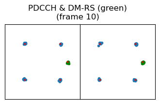
With this information it is now possible to wipe off the PDCCH DM-RS symbols. The figure below shows the constellation of the two PDCCH symbols. Data symbols are shown in blue, and wiped-off DM-RS symbols are shown in green.
The CSI-RS and the TRS begin at subcarrier 116, which is one resource block below the start of CORESET 0. I think that these CSI-RS must occupy the whole cell. In fact, they occupy the subcarriers from 116 (included) to 416 (not included). This is a total of 25 resource blocks, which is what a 5 MHz cell uses. Therefore, it seems that CORESET 0 starts at resource block 1 (numbering the first resource block in the cell as 0). Interestingly, the PDSCH transmission for SIB1 also starts at resource block 1.
Code and data
I have updated the Jupyter notebook with the work that I have done in this post. The recording can be found in the same repository.
2 comments