GNSS interferometry at Allen Telescope Array

Since the beginning of October, together with a group of people from the GNU Radio community, we are doing some experiments and tests remotely at Allen Telescope Array (ATA). This amazing opportunity forms part of the recent collaboration agreement between SETI Institute and GNU Radio. We are taking advantage of the fact that the ATA hardware is relatively unused on weekends, and putting it to good use for our experiments. One of the goal of these activities is to put in contact GNU Radio people and radio astronomy people, to learn from each other and discover what features of GNU Radio could benefit radio astronomy and SETI, particularly at the ATA.

I’m very grateful to Wael Farah, Alex Pollak, Steve Croft and Ellie White from ATA and SETI Institute for their support of this project and the very interesting conversations we’ve had, to Derek Kozel, who is Principal Investigator for GNU Radio at SETI, for organizing and supporting all this, and to the rest of my GNU Radio teammates for what’s being an excellent collaboration of ideas and sharing of resources.

From the work I’ve been doing at ATA, I already have several recordings and data, and also some studies and material that I’ll be publishing in the near future. Hopefully this post will be the first in a series of many.

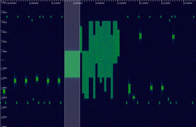
Here I will speak about one of the first experiments I did at ATA, which is a recording of one Galileo GNSS satellite using two of the dishes from the array. This kind of recording can be used to perform interferometry. GNSS satellites are good test targets because they have strong wideband signals and their location is known precisely. The IQ recording described in this post is published as the dataset “Allen Telescope Array Galileo E31 RF recording with 2 antennas and 2 polarizations” in Zenodo.

Coherence and QO-100

My tweet about the AMSAT-BR QO-100 FT8 QRPp experiment has spawned a very interesting discussion with Phil Karn KA9Q, Marcus Müller and others about weak signal modes specifically designed for the QO-100 communications channel, which is AWGN albeit with some frequency drift (mainly due to the imperfect reference clocks used in the typical groundstations).

Roughly speaking, the conversation shifted from noting that FT8 is not so efficient in terms of EbN0 to the idea of using something like coherent BPSK with \(r=1/6\) CCSDS Turbo code, then to observing that maybe there was not enough SNR for a Costas loop to work, so a residual carrier should be used, and eventually to asking whether a residual carrier would work at all.

There are several different problems that can be framed in this context. For me, the most interesting and difficult one is how to transmit some data with the least CN0 possible. In an ideal world, you can always manage to transmit a weaker signal just by transmitting slower (thus maintaining the Eb/N0 constant). In the real world, however, there are some time-varying physical parameters of the signal that the receiver needs to track (be it phase, frequency, clock synchronization, etc.). In order to detect and track these parameters, some minimum signal power is needed at the receiver.

This means that, in practice, depending on the physical channel in question, there is a lower CN0 limit at which communication on that channel can be achieved. In many situations, designing a system that tries to approach to that limit is a hard and interesting question.

Another problem that can be posed is how to transmit some data with the least Eb/N0 possible, thus approaching the Shannon capacity of the channel. However, the people doing DVB-S2 over the wideband transponder are not doing it so bad at all in this respect. Indeed, by transmitting faster (and increasing power, to keep the Eb/N0 reasonable), the frequency drift problems become completely manageable.

In any case, if we’re going to discuss about these questions, it is important to characterize the typical frequency drift of signals through the QO-100 transponder. This post contains some brief experiments about this.

Simulating the TED gain for a polyphase matched filter

Trying to improve the performance of the demodulators in gr-satellites, I am switching to the Symbol Sync GNU Radio block, which was introduced by Andy Walls in GRCon17. This block covers the functionality of all the other clock synchronization blocks, such as Polyphase Clock Sync and Clock Recovery MM, while fixing many bugs.

One of the new features of the Symbol Sync block is the ability to specify the gain of the timing error detector (TED) used in the clock recovery feedback loop. All the other blocks assumed unity gain, which simply causes the loop filter taps to be wrong. However, the TED gain needs to be calculated beforehand either by analysis or simulation, as it depends on the choice of TED, samples per symbol, pulse shaping, SNR and other.

While Andy shows how to use the Symbol Sync block as a direct replacement for the Polyphase Clock Sync block in his slides, he leaves the TED gain as one, since that is what the Polyphase Clock Sync block uses. In replacing the Polyphase Clock Sync block by Symbol Sync in gr-satellites, I wanted to use the correct TED gain, but I didn’t found anyone having computed it before. This post shows my approach at simulating the TED gain for polyphase matched filter with maximum likelyhood detector.

Receiving a LoRa high altitude balloon

Last Sunday, Julián Fernández EA4HCD, released a high altitude balloon carrying a LoRa payload as a preliminary test for the FossaSat-1 pocketqube that he is devolping with Fossa Systems. You can see a video of the release in this tweet. The balloon was launched near Madrid, and burst at an altitude of approximately 24km, having travelled some 180km southeast.

The payload had two transmitters: An SX1278 LoRa transceiver transmitting at 434.5MHz with 10mW alternating between LoRa and RTTY, and an 868MHz 25mW LoRa transceiver that was received on The Things Network. Simple groundplane 1/4-wave monopole antennas were used.

I went to the countryside just outside my city, Tres Cantos, and set up a station to record the transmissions on 434.5MHz. The station consisted of a 7 element yagi by Arrow Antennas, set in vertical polarization and placed on a camera tripod on the roof of my car, and a FUNcube Dongle Pro+. This is a brief analysis of the recording.

Results of DSLWP-B Amateur VLBI experiment on 2018-11-21

The first Amateur VLBI experiment with DSLWP-B was performed on 2018-06-10. In that experiment, the 250baud GMSK beacons at 435.4MHz and 436.4MHz were recorded in the 25m PI9CAM radiotelescope in Dwingeloo, The Netherlands, and a 12m repurposed Inmarsat C-band dish in Shahe, Beijing. These synchronized recordings were processed later to obtain delta-range and delta-velocity measurements. Due to the low baudrate, the noise of the delta-range measurements was quite high, on the order of 20km. Since the beacons were short transmissions of 15 seconds, making accumulated phase measurements was not possible.

Another Amateur VLBI experiment was performed on 2018-11-21. The novelty of this experiment was that 500baud GMSK SSDV transmissions were made on 436.4MHz. These long transmissions, lasting around 30 minutes each, allow us to make accumulated phase measurements. Also, the higher baudrate reduces the noise in the delta-range measurements. Another novelty was that a third station, the Harbin Institute of Technology Amateur Radio Club BY2HIT groundstation also joined the experiments, so observations from three stations are available.

This post is an account of the results I have obtained processing the observations from 2018-11-21.

Detecting the Sprites from KickSat-2

The Sprites chipsats are tiny satellites built on a 3.5×3.5cm PCB with the bare minimum electronics to do something useful: a CC430 microcontroller with integrated FSK transceiver, an IMU, and solar cells.

Sprite chipsat (taken from the KickSat webpage)

The Sprites have been developed as part of the KickSat project, led by Zac Manchester, from Stanford University. The idea is to carry up to 128 Sprites in a cubesat and deploy them in a swarm once the cubesat is in orbit. The first test of this concept was done by the KickSat 3U cubesat in 2014. The test was a failure, since the Sprites couldn’t be deployed before KickSat reentered.

The second test was made this year with the KickSat-2 3U cubesat, a reflight of the KickSat mission carrying 104 Sprites. KickSat-2 was launched to the ISS onboard Cygnus NG-10 in November 2018 and deployed into orbit in February 2019.

On March 19, the Sprites were successfully deployed from KickSat-2, as Zac announced in Twitter, requesting help from the Amateur radio community to receive the signals from the Sprites at 437.240MHz. On March 22, Cees Bassa and Tammo Jan Dijkema tried to detect the Sprites by doing a planar scan with the Dwingeloo 25m radiotelescope. They were successful, detecting several transmissions from the Sprites in the waterfall. At that moment, the Sprites were up to 5 minutes ahead KickSat-2, due to their much higher drag to mass ratio. They all probably reentered a few days after this.

All the Sprites transmit in the same frequency using CDMA, so further analysis is required to identify which Sprites were observed by Dwingeloo. Zac said he was working on decoding the recording, however, I haven’t seen any results published yet. Here I show my analysis of the recording made at Dwingeloo. I manage to detect 4 different Sprites.

Recovering an image transmitted by DSLWP-B

The image accompanying this post has a nice story to it. It was taken by the Amateur camera in DSLWP-B, the Chinese microsatellite in lunar orbit. On February 27, a download of this image was attempted by transmitting the image in SSDV format in the 70cm band and receiving it in the Dwingeloo radiotelescope, in the Netherlands.

The download was attempted twice, but due to errors in the transmission, a small piece of the image was still missing. Today, the Amateur payload of DSLWP-B was active again, and the plan was to download the missing piece, as well as other images. However, after the payload turned on and transmitted its first telemetry beacons, we discovered that the image had been overwritten.

The camera on-board DSLWP-B has a buffer that stores the last 16 images taken. Any of these images can be selected to be transmitted (completely or partially) while the Amateur payload is active. An image can be taken manually by issuing a command from ground. Besides this, every time the Amateur payload powers on, an image is taken. Of course, taking new images overwrites the older ones.

This is what happened today. The image we wanted to download was the oldest one in the buffer and got overwritten as soon as the payload turned on. This is a pity, especially because there was another activation of the payload last Friday, but a large storm in Germany prevented Reinhard Kuehn DK5LA’ from moving his antennas safely, so the satellite couldn’t be commanded to start the download.

After seeing that the image had been overwritten, Tammo Jan Dijkema suggested that I try to recover manually the missing chunk in the recording made on February 27. As you can see, I was successful. This is a report of how I proceeded.

Batch processing of DSLWP-B Moonbounce: part I

In previous posts I’ve talked about how the DSLWP-B 70cm signal can sometimes be received in the Dwingeloo 25m radiotelescope via a reflection off the Moon’s surface. I’ve studied the geometry of this reflection, the cross-correlation against the direct signal, and even decoded some reflected JT4G.

However, so far the reflection has been detected by hand by looking at the recording waterfalls. We don’t have any statistics about how often it happens or which conditions favour it. I want to make some scripts to process all the Dwingeloo recordings in batch and try to extract some useful conclusions from the data.

Here I show my first script, which computes the power of the direct and reflected signals (if any). The analysis of the results will be done in a future post.

Decoding TANUSHA-3

On August 15, during a Russian EVA on the ISS, a total of four Russian nanosatellites were deployed by hand. Although different online sources give incomplete and contradictory information about which satellites were released, it seems that they were SiriusSat 1 and 2, from the Sirius educational centre in Sochi, and Tanusha 3 and 4 from the Southwest State University in Kursk (see also Jonathan McDowell’s space report).

The SiriusSats are using 4k8 FSK AX.25 packet radio at 435.570MHz and 435.670MHz respectively, using callsigns RS13S and RS14S. The Tanushas transmit at 437.050MHz. Tanusha-3 normally transmits 1k2 AFSK AX.25 packet radio using the callsign RS8S, but Mike Rupprecht sent me the other day a recording of a transmission from Tanusha-3 that he could not decode.

It turns out that the packet in this recording uses a very peculiar modulation. The modulation is FM, but the data is carried in audio frequency phase modulation with a deviation of approximately 1 radian. The baudrate is 1200baud and the frequency for the phase modulation carrier is 2400Hz. The coding is AX.25 packet radio.

Why this peculiar mode is used in addition to the standard 1k2 packet radio is a mystery. Mike believes that the satellite is somehow faulty, since the pre-recorded audio messages that it transmits are also garbled (see this recording). If this is the case, it would be very interesting to know which particular failure can turn an AFSK transmitter into a phase modulation transmitter.

I have added support to gr-satellites for decoding the Tanusha-3 phase modulation telemetry. To decode the standard 1k2 AFSK telemetry direwolf can be used. The decoder flowgraph can be seen in the figure below.

TANUSHA-3 gr-satellites decoder

The FM demodulated signal comes in from the UDP source. It is first converted down to baseband and then a PLL is used to recover the carrier. The Complex to Arg block recovers the phase, yielding an NRZ signal. This signal is lowpass filtered, and then clock recovery, bit slicing and AX.25 deframing is done. Note that it is also possible to decode this kind of signal differentially, without doing carrier recovery, since the NRZI encoding used by AX.25 is differential. However, the carrier recovery works really well, because there is a lot of residual carrier and this is an audio frequency carrier, so it should be very stable in frequency.

The recording that Mike sent me is in tanusha3_pm.wav. It contains a single AX.25 packet that when analyzed in direwolf yields the following.

RS8S>ALL:This is SWSU satellite TANUSHA-3 from Russia, Kursk<0x0d>
------
U frame UI: p/f=0, No layer 3 protocol implemented., length = 68
 dest    ALL     0 c/r=1 res=3 last=0
 source  RS8S    0 c/r=0 res=3 last=1
  000:  82 98 98 40 40 40 e0 a4 a6 70 a6 40 40 61 03 f0  ...@@@...p.@@a..
  010:  54 68 69 73 20 69 73 20 53 57 53 55 20 73 61 74  This is SWSU sat
  020:  65 6c 6c 69 74 65 20 54 41 4e 55 53 48 41 2d 33  ellite TANUSHA-3
  030:  20 66 72 6f 6d 20 52 75 73 73 69 61 2c 20 4b 75   from Russia, Ku
  040:  72 73 6b 0d                                      rsk.
------

The contents of the packet are a message in ASCII. The message is of the same kind as those transmitted in AFSK.

Detecting meteor scatter pings from GRAVES during the Perseids

GRAVES is a French space surveillance radar that transmits with very high power at 143.050MHz. It is easy to receive it from neighbouring countries via meteor scatter. During this year’s Perseids meteor shower I did a recording of GRAVES and the 2m Amateur band for later analysis. The recording was done at 08:56 UTC of Saturday 12th August and it is about 1 hour and 34 minutes long. Here I present an algorithm to detect and extract the meteor scatter pings from GRAVES.