Here I want to show a technique for measuring the gain of a dish that I first learned from an article by Christian Monstein about the Moon’s temperature at a wavelength of 2.77cm. The technique only uses power measurements from an observation of a radio source, at different angles from the boresight. Ideally, the radio source should be strong and point-like. It is also important that the angles at which the power measurements are made are known with good accuracy. This can be achieved either with a good rotator or by letting an astronomical object drift by on a dish that is left stationary.
Tag: microwaves
Transmitting through QO-100 with the LimeNET Micro and LimeRFE
A couple weeks ago, I did a demo where I showed the LimeRFE radio frequency frontend being used as an HF power amplifier to transmit WSPR in the 10m band. Another demo I wanted to do was to show the LimeNET Micro and LimeRFE as a standalone 2.4GHz transmitter for the QO-100 Amateur radio geostationary satellite.
The LimeNET Micro can be best described as a LimeSDR plus Raspberry Pi, so it can be used as an autonomous transceiver or remotely through an Ethernet network. The LimeRFE has a power amplifier for 2.4GHz. According to the specs, it gives a power of 31dBm, or a bit over 1W. This should be enough to work QO-100 with a typical antenna.
You may have seen the field report article about the QO-100 groundstation I have in my garden. It is based around a LimeSDR Mini and BeagleBone Black single board ARM computer. The groundstation includes a driver amplifier that boosts the LimeSDR to 100mW, and a large power amplifier that gives up to 100W. The LimeSDR Mini and BeagleBone Black give a very similar functionality to the LimeNET Micro, but the LimeNET Micro CPU is more powerful.
The idea for this demo is to replace my QO-100 groundstation by the LimeNET Micro and LimeRFE, maintaining only the antenna, which is a 24dBi WiFi grid parabola, and show how this hardware can be used as a QO-100 groundstation.
Second Moon observation with my QO-100 station.
In May 25, the Moon passed through the beam of my QO-100 groundstation and I took the opportunity to measure the Moon noise and receive the Moonbounce 10GHz beacon DL0SHF. A few days ago, in July 22, the Moon passed again through the beam of the dish. This is interesting because, in contrast to the opportunity in May, where the Moon only got within 0.5º of the dish pointing, in July 22 the Moon passed almost through the nominal dish pointing. Also, incidentally this occasion has almost coincided with the 50th anniversary of the arrival to the Moon of Apollo 11, and all the activities organized worldwide to celebrate this event.
The figure below shows the noise measurement at 10366.5GHz with 1MHz and a 1.2m offset dish, compared with the angular separation between the Moon and the nominal pointing of the dish (defined as the direction from my station to Es’hail 2). The same recording settings as in the first observation were used here.
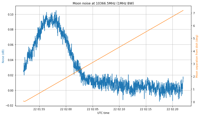
The first thing to note is that I made a mistake when programming the recording. I intended to make a 30 minute recording centred at the moment of closest approach, but instead I programmed the recording to start at the moment of closest approach. The LimeSDR used to make the recording was started to stream one hour before the recording, in order to achieve a stable temperature (this was one lesson I learned from my first observation).
The second comment is that the maximum noise doesn’t coincide with the moment when the Moon is closest to the nominal pointing. Luckily, this makes all the noise hump fit into the recording interval, but it means that my dish pointing is off. Indeed, the maximum happens when the Moon is 1.5º away from the nominal pointing, so my dish pointing error is at least 1.5º. I will try adjust the dish soon by peaking on the QO-100 beacon signal.
The noise hump is approximately 0.085dB, which is much better than the 0.05dB hump that I obtained in the first observation. It may not seem like much, but assuming the same noise in both observations, this is a difference of 2.32dB in the signal. This difference can be explained by the dish pointing error.
The recording I have made also covers the 10GHz Amateur EME band, but I have not been able to detect the signal of the DL0SHF beacon. Perhaps it was not transmitting when the recording was made. I have also arrived to the conclusion that the recording for my first observation had severe sample loss, as it was made on a mechanical hard drive. This explains the odd timing I detected in the DL0SHF signal.
The next observation is planned for October 11, but before this there is the Sun outage season between September 6 and 11, in which the Sun passes through the beam of the dish, so that Sun noise measurements can be performed.
First Moon observation with my QO-100 station
A month ago, I spoke about planning the passes of the Moon through the beam of my QO-100 station. These give an occasion to observe the Moon without moving a dish that is pointing to Es’hail 2. The next opportunity after writing that post was on May 16 at 20:16 UTC.
Since I wasn’t going to be at home at that time, I programmed my computer to make a recording for later analysis. I recorded 4MHz of spectrum centred at 10367.5MHz using a LimeSDR connected to the LNB that I use to receive QO-100. The recording was planned to be 30 minutes long starting at 20:01 UTC, but for some reason only approximately 27 minutes were recorded.
This kind of events can be used to measure Moon noise and receive 10GHz EME signals. This post is an analysis of my recording, looking at these two things.
Rain fade in the QO-100 downlink
The Amateur transponders of Es’hail 2 have their downlink in the 10GHz Amateur band. Even though the path to the satellite through the atmosphere is rather short, in extreme weather conditions it is possible to observe a small amount of fading in the signal. Two days ago there was intense rain over Madrid. As I’m often recording the power of the narrowband transponder beacons and the transponder noise floor, I have examined my data to see if the effect of the rain is visible.
The data is plotted in the figure below. See this post for an explanation of the measurements.
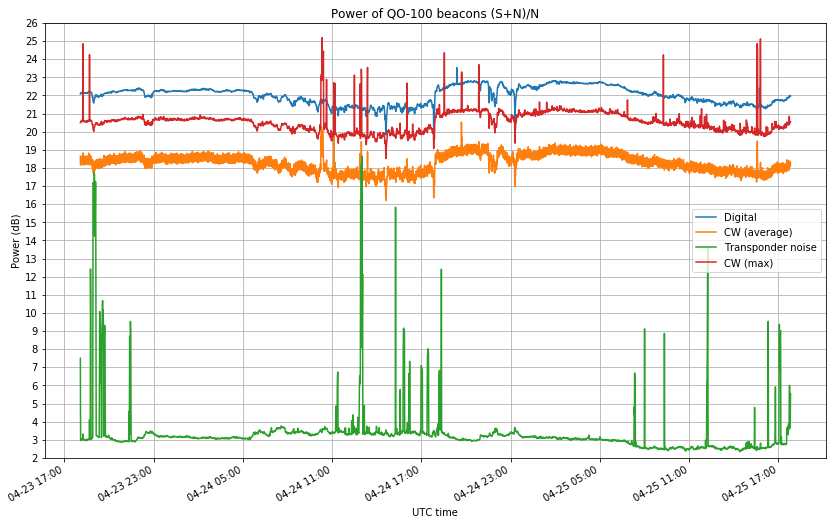
The power of the beacons is not very stable. It can vary up to 2 or 3dB along the course of the day. Therefore, it is not so easy to measure the drop in signal power caused by rain. However, it is noticeable that on April 24, between 05:00 and 17:00 UTC, the power of the beacons varies much more rapidly than usually. A small ripple of 0.5dB of amplitude is visible on the data. I think that this ripple is caused by varying rain intensity. Therefore, the data seems to suggest that the rains two days ago caused up to 0.5dB of fading in the signal.
As seen from my station, the satellite is at an elevation of \(\theta = 33.6^\circ\), so assuming a slant factor of \(1/\sin \theta = 1.8\), so taking a typical height of around 1km for the column of rain (see the corresponding METAR for Madrid airport), we get an attenuation on the order of 0.3dB/km. However, all the measurements used here are too imprecise to obtain any good conclusions. See this related post, in which I measured a 2.5dB increase in the noise floor at 12GHz during a hailstorm, but no change in signal power.
QO-100 beacons power
In the QO-100 (Es’hail 2) narrow band transponder, the recommendation for the adjustment of your downlink signal power is not to be stronger than the beacon. This was also the recommended usage of the old AO-40. Since the transponder has two beacons marking the transponder edges: a CW beacon marking the lower edge and a 400baud BPSK beacon marking the upper edge, there has been some debate on Twitter about which beacon does this recommendation refer to and what does “stronger” mean.
Of course, more formally, signal strength means power, which is a well defined physical concept, so there should be no argument about what does power mean. However, there are two different power measurements used for RF: average power and peak envelope power. I will assume that the recommendation refers to average power, not to peak envelope power. This makes more sense from the point of view of the power budget of the satellite amplifier (The total average power it needs to deliver is just the sum of the average powers of the signals of all the users, while the behaviour of the peak envelope power is much more complicated).
Also, I think that using peak envelope power for this restriction would be a very strict requirement on high PAPR signals. Note that the PAPR of CW is 0dB and the PAPR of BPSK is between 2 and 3dB, depending on the pulse shaping, so these are rather low PAPRs. For comparison, a moderately compressed SSB voice signal has a PAPR of 6dB.
In my opinion, the main problem with these discussions about “signal strength” is that many people are trying to judge power by looking at their waterfall or spectrum display and seeing what signal looks “higher”. This kind of measurement is not any good, because it doesn’t take signal bandwidth into account, depends on the FFT size, the window function, etc. It doesn’t help that many popular SDR software don’t have a good signal meter displaying the average power of the signal tuned in the passband.
In any case, I was curious about whether the power of the two beacons is the same and whether there is any interesting change over time. I have made a GNU Radio flowgraph that measures the power of each of the two beacons and of the transponder noise, and saves them to a file for later analysis.
Decoding the QO-100 beacon with gr-satellites
On February 14, the Amateur transponders on Es’hail 2 (which now has the AMSAT designation QO-100) were inaugurated. Since then, two beacons are being transmitted by the groundstation in Doha (Qatar) through the narrowband transponder. These beacons mark the edges of the transponder.
The lower beacon is CW, while the upper beacon is a 400baud BPSK beacon that uses the same format as the uncoded beacon of AO-40. I have already talked about the AO-40 uncoded beacon in an older post, including the technical details.
Based on my AO-40 decoder in gr-satellites, I have made a decoder for the QO-100 beacon. Patrick Dohmen DL4PD has been kind enough to write some instructions about how to use the old ao40_uncoded decoder with the BATC WebSDR. I recommend that you use the new qo100 decoder. You just have substitute ao40_uncoded by qo100 in Patrick’s instructions
As additional hints, I can say that for the best decoding, the beacon must be centred at 1.5kHz into the SSB passband. The centre of the signal is easy to spot because there is a null at the centre, due to the use of Manchester encoding. Frequency stability is somewhat important with this decoder, so if your LNB drifts too much you may run into problems.
The SNR of the beacon over the transponder noise floor is rather high, so you should achieve a clean decoding unless you are using a very small station and you have the transponder noise way below your receiver noise floor.
The following data is being currently transmitted on the beacon (the timestamps and packet numbers are added by gr-satellites):
2019-02-19 21:56:27
Packet number 68
K HI de QO-100 (DL50AMSAT BOCHUM
UPT: 3d 0h 29m CMD: 91 LEI_REQ: 0 LEI_ACT: 0
TEMP: 56 C VOLTAGES: 1.0 1.8 1.0 1.0 1.8 1.5 1.3 0.0 0.5 Volts
TFL: 0 TFE: 0 TFH: 0 HFF: 0 HTH: 0 HR: 0
2019-02-19 21:56:53
Packet number 69
L HI de QO-100 (DL50AMSAT BOCHUM
EXPERIMENTAL MODE. Measurements and tests being conducted,
experimental transponder use OK, but expect ground station tests
Watch this space and www.amsat-dl.org for further announcements
In-orbit testing of Es’hail 2 Amateur transponders
Yesterday, December 23, MELCO carried out some in-orbit tests of the Es’hail 2 Amateur radio transponders. Since Es’hail 2 is currently under commissioning, it was expected that at some point the Amateur transponders would be activated for testing, but no announcement of the tests was done in advance. At around 11:00 UTC, Rob Janssen PE1CHL, noticed that the narrowband transponder was active and a carrier signal was being transmitted through it.
Since then, I monitored most of the tests and sent updates on Twitter, together with other people (see also the posts in the AMSAT-DL forum). Without knowing the details of the test plans, we limited ourselves to watching and following the tests that were being made. If some schedule of the tests had been published in advanced, we could have thought, prepared and performed some interesting measurements on the downlink signals.
I understand that since these tests are carried out by MELCO, AMSAT-DL might not have the specific details, but still I think that AMSAT-DL is publishing very little information about Es’hail 2 events. It was only at 22:35 UTC that AMSAT-DL published a small note on Twitter about the tests. I think the greatest concern is that people start transmitting through the transponder, interfering with the tests. However, since news spread very fast these days through social media, I think that publishing more information rather than keeping things discreetly serves better to prevent people from using the transponder during the commissioning. In any case, I’ll repeat it here:
Es’hail 2 is currently under commissioning. The 2.4GHz uplink of the Amateur transponders should never be used until authorized by AMSAT-DL. The Amateur transponders will sometimes be enabled for in-orbit testing by the MELCO/Es’hailSat/AMSAT-DL engineers. Relax, sit back, and watch the tests on the 10GHz downlink.
I also think that publishing more information would be beneficial to educate the community of radio Amateurs. Some people have asked me about the concept of in-orbit tests. After a satellite is launched into orbit, the performance of all its systems is tested to ensure that it matches design specifications, simulations, and pre-launch tests done on ground. This is important to guarantee that any problems, malfunction or damage that occurred during the launch can be diagnosed and hopefully mitigated by activating backup systems or other reliability measures. In-orbit testing of large satellites can take several months, since there are many complex systems that need to be tested remotely.
In the case of the Amateur radio payload of Es’hail 2, MELCO is carrying out the tests, since the payload was built by MELCO according to the design specifications by AMSAT-DL. The kind of tests they are performing are related to the performance of the bent-pipe transponders. They sweep in frequency the transponders to make sure that the passband shape is as expected. They transmit carriers of different power levels to check for linearity of the transponder and AGC performance, and they try different gain/power level settings of the transponder power amplifier to make sure it performs correctly over all its working range.
This is a rough account of the tests that were made yesterday, using my tweets as a sort of activity log.
Recommendations for receiving Es’hail 2
A couple days ago, Janos Tolgyesi HG5APZ asked me by email about different hardware setups to receive the Amateur radio transponders on Es’hail 2, with an interest on inexpensive but effective solutions. He was quite happy with my detailed reply and convinced me to turn it into a blog post, so that other people can learn from it.
This post is intended for people that do not know much about Es’hail 2 but are interested in receiving it. If you’ve been investigating about the different setups that people are doing to receive it, then probably you’ll not learn anything new here. The post addresses questions such as “do I need a modified LNB” and similar.
Aircraft reflections of a 2.3GHz beacon
A couple months ago, Andrés Calleja EB4FJV installed a 2.3GHz beacon in his home in Colmenar Viejo, Madrid. The beacon has 2W of power, radiates with an omnidirectional antenna in the vertical polarization, and transmits a tone and CW identification at the frequency 2320.865MHz.
Since Colmenar Viejo is only 10km away from Tres Cantos, where I live, I can receive the beacon with a very strong signal from home. The Madrid-Barajas airport is also quite near (15km to the threshold of runway 18R) and several departure and approach aircraft routes pass nearby, particularly those flying over the Colmenar VOR. Therefore, it is quite easy to see reflections off aircraft when listening to the beacon.
On July 8 I did a recording of the beacon from 10:04 to 11:03 UTC from the countryside just outside Tres Cantos. In this post I will examine the aircraft reflections seen in the recording and match them with ADS-B aircraft position and velocity data obtained from adsbexchange.com. This will show the locations and trajectories which produce reflections strong enough to be detected.