Update on the QO-100 local oscillator wiggles

This post is a follow up to my study of the “wiggles” observed in the local oscillator of the QO-100 NB transponder. After writing that post, I have continued measuring the frequency of the BPSK beacon with my station almost without interruptions. Now I have some 44 days of measurements, spanning from April 9 to May 23. This data can be interesting to look at, so I’m doing this short post to share the data and look at it briefly.

The Jupyter notebook with all the data can be found here. The data is also linked in my jupyter_notebooks Github repository, which now uses git-annex to store the data in my home server. See the README for instructions on how to download some or all of the data files in the repository.

The whole time series can be seen in the figure below. We note that the typical Doppler sinusoidal curve varies slowly due to orbit perturbations and sometimes suddenly as a consequence of a station-keeping manoeuvre. I tweeted about one of the manoeuvres a while back.

There are now too many days in order to see things clearly when the frequency curves for each day are overlaid, but hopefully the figure below gives a good idea. We can see that the wiggles still happen approximately between 21:00 and 06:00 UTC, and between 11:00 and 17:00 UTC.

If we add an artificial offset of -15 Hz per day to the curves to prevent them from overlapping, we obtain the figure below. We see that the pattern of the wiggles keeps changing slightly, but also remains quite similar.

In my last post about this topic I said that it seemed that the wiggles repeated with a period of a sidereal day. Now it is clear that it is not the case. The wiggles seem to repeat roughly with a period of a solar day (24 hours). In fact, in 44 days sidereal time “advances” 2.88 hours with respect to solar time. However, it is clear that the wiggles haven’t shifted that much in time.

Wiggles in the QO-100 local oscillator

Some days ago, Hans Hartfuss DL2MDQ sent me an email about some frequency measurements of the QO-100 NB transponder BPSK beacon that he had been doing. The BPSK beacon is uplinked from Bochum (Germany) through the transponder, and as the beacon is generated using a very good Z3081A GPSDO as a reference, the frequency drift observed on the beacon downlink is caused by Doppler and the drift of the local oscillator of the transponder.

In his measurements, Hans observed some small oscillations or “wiggles” that didn’t seem to be caused by Doppler. Decided to investigate this, I started to do some measurements of my own. This post is an account of my measurements and findings so far.

Coherence and QO-100

My tweet about the AMSAT-BR QO-100 FT8 QRPp experiment has spawned a very interesting discussion with Phil Karn KA9Q, Marcus Müller and others about weak signal modes specifically designed for the QO-100 communications channel, which is AWGN albeit with some frequency drift (mainly due to the imperfect reference clocks used in the typical groundstations).

Roughly speaking, the conversation shifted from noting that FT8 is not so efficient in terms of EbN0 to the idea of using something like coherent BPSK with \(r=1/6\) CCSDS Turbo code, then to observing that maybe there was not enough SNR for a Costas loop to work, so a residual carrier should be used, and eventually to asking whether a residual carrier would work at all.

There are several different problems that can be framed in this context. For me, the most interesting and difficult one is how to transmit some data with the least CN0 possible. In an ideal world, you can always manage to transmit a weaker signal just by transmitting slower (thus maintaining the Eb/N0 constant). In the real world, however, there are some time-varying physical parameters of the signal that the receiver needs to track (be it phase, frequency, clock synchronization, etc.). In order to detect and track these parameters, some minimum signal power is needed at the receiver.

This means that, in practice, depending on the physical channel in question, there is a lower CN0 limit at which communication on that channel can be achieved. In many situations, designing a system that tries to approach to that limit is a hard and interesting question.

Another problem that can be posed is how to transmit some data with the least Eb/N0 possible, thus approaching the Shannon capacity of the channel. However, the people doing DVB-S2 over the wideband transponder are not doing it so bad at all in this respect. Indeed, by transmitting faster (and increasing power, to keep the Eb/N0 reasonable), the frequency drift problems become completely manageable.

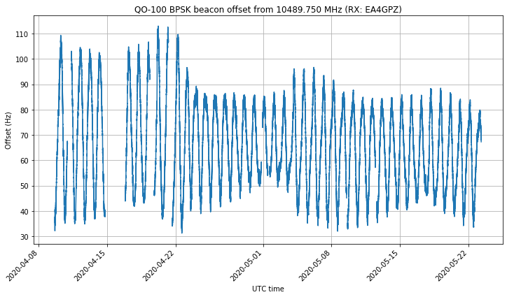
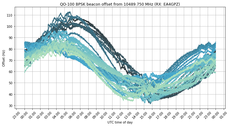
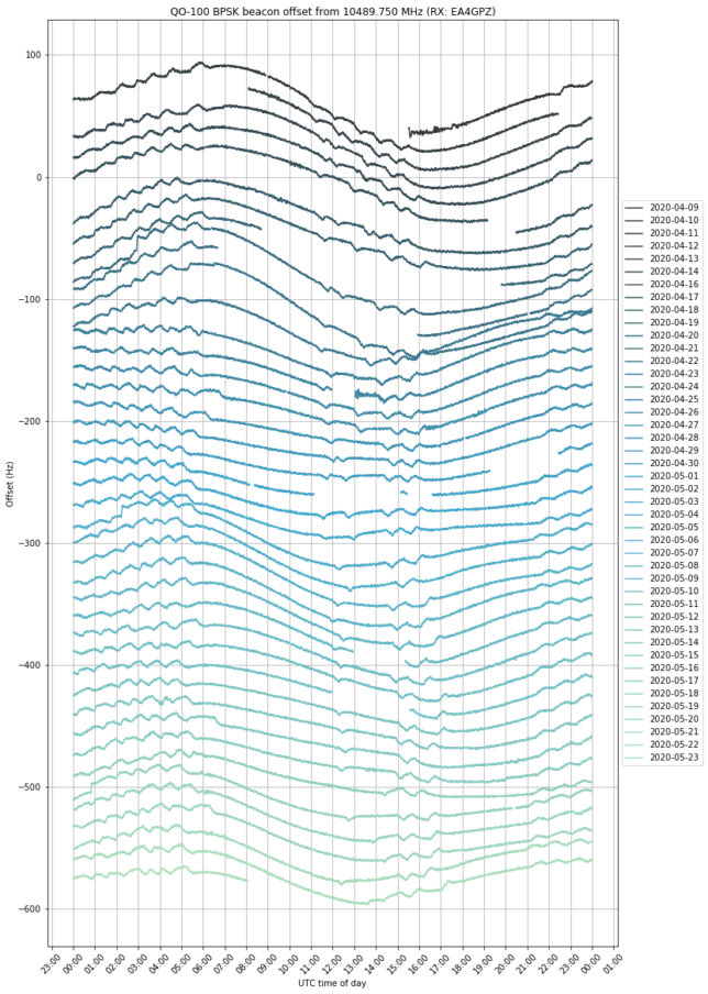
In any case, if we’re going to discuss about these questions, it is important to characterize the typical frequency drift of signals through the QO-100 transponder. This post contains some brief experiments about this.

QO-100 BPSK beacon frequency measured at Bochum

The experiments about measuring the frequency stability of the local oscillator of the QO-100 NB transponder with a Vectron MD-011 GPSDO I made a few days ago indicated that the Allan deviation of the local oscillator was probably better than \(10^{-11}\) for \(\tau\) between 1 and 100 seconds. The next step in trying to characterize the stability of the local oscillator is to use a reference clock which is more stable than the Vectron.

I contacted Achim Vollhardt DH2VA asking him if it was possible to record the downlink of the BPSK beacon at Bochum, so as to have a recording referenced to the Z3801A GPSDO in Bochum, which is much more stable than the Vectron. He and Mario Lorenz DL5MLO have been very kind and they have taken the effort to make a recording for me. This post is an analysis of this recording made at Bochum.

More frequency measurements of the QO-100 NB transponder

This post is a follow up to my experiments about measuring the stability of the QO-100 NB transponder local oscillator. I am now using the Vectron MD-011 GPSDO that Carlos Cabezas EB4FBZ has lent me to reference all my QO-100 groundstation (see more information about the Vectron GPSDO in this post).

The Vectron MD-011 has an Allan deviation of \(10^{-11}\) at \(\tau = 1\,\mathrm{s}\) and \(2\cdot10^{-11}\) at \(\tau = 10\,\mathrm{s}\) according to the datasheet, so it is an improvement of an order of magnitude compared to my DF9NP TCXO-based GPSDO. I have made more measurements with the Vectron MD-011 as in my previous experiments, measuring the phase of the BPSK beacon transmitted from Bochum and a CW tone transmitted with my station. This post summarizes my results and conclusions.

Can my station measure the QO-100 NB transponder LO stability?

Following a long discussion with Bernd Zoelgert DL2BZ about the frequency stability of the local oscillator of the QO-100 narrowband transponder, I have decided to try to measure the Allan deviation of the transponder. The focus here is on short-term stability, so we are concerned with observation intervals around \(\tau = 1 \mathrm{s}\).

Of course, as with any measurement problem, the performance of the measurement equipment should be better than the “device under test”. In this case, to measure the QO-100 LO it is necessary to compare it against a reference clock which is more stable (ideally an order of magnitude better).

My whole station is locked to a DF9NP GPSDO, which is a 10MHz VCTCXO disciplined by a uBlox LEA-4S GPS receiver. That’s great to measure long-term stability, but for short-term measurements you are essentially relying on the stability of the VCTCXO, which is not so great. Therefore, the whole purpose of this experiment is first to determine whether my station is actually able to measure the QO-100 LO or not. Spoiler: it turns out the answer is “no”, as in most articles whose title is phrased as a question.

Sun observations at 10GHz

Around October 9 it was the sun outage season for Es’hail 2 as seen from Madrid. This means that the sun passed behind Es’hail 2, so it was the perfect occasion to observe the sun with my QO-100 groundstation, which has a 1.2m offset dish antenna pointing to Es’hail 2. This is an account of the measurements I made, and their use to evaluate the receiver performance.

Measuring the ED4YAE 10GHz beacon

Last week, the 10GHz beacon ED4YAE on Alto del León was installed again after having been off the air for quite some time (I think a couple of years). The beacon uses a 10MHz OCXO and a 500mW power amplifier, and transmits CW on 10368.862MHz. The message transmitted by the beacon is DE ED4YAE ED4YAE ED4YAE IN70WR30HX, followed by a 5.8 second long tone.

On 2019-08-31, I went to the countryside just outside my city, Tres Cantos, to receive the beacon and do some measurements. The measurements were done around 10:00 UTC from locator IN80DO68TW. The receiving equipment was a 60cm offset dish from diesl.es, an Avenger Ku band LNB, and a LimeSDR USB. Everything was locked to a 10MHz GPSDO. The dish was placed on a camera tripod at a height of approximately 1.5 metres above the ground.

In this post I show the results of my measurements.

Measuring the gain of a dish

Here I want to show a technique for measuring the gain of a dish that I first learned from an article by Christian Monstein about the Moon’s temperature at a wavelength of 2.77cm. The technique only uses power measurements from an observation of a radio source, at different angles from the boresight. Ideally, the radio source should be strong and point-like. It is also important that the angles at which the power measurements are made are known with good accuracy. This can be achieved either with a good rotator or by letting an astronomical object drift by on a dish that is left stationary.

Transmitting through QO-100 with the LimeNET Micro and LimeRFE

A couple weeks ago, I did a demo where I showed the LimeRFE radio frequency frontend being used as an HF power amplifier to transmit WSPR in the 10m band. Another demo I wanted to do was to show the LimeNET Micro and LimeRFE as a standalone 2.4GHz transmitter for the QO-100 Amateur radio geostationary satellite.

The LimeNET Micro can be best described as a LimeSDR plus Raspberry Pi, so it can be used as an autonomous transceiver or remotely through an Ethernet network. The LimeRFE has a power amplifier for 2.4GHz. According to the specs, it gives a power of 31dBm, or a bit over 1W. This should be enough to work QO-100 with a typical antenna.

You may have seen the field report article about the QO-100 groundstation I have in my garden. It is based around a LimeSDR Mini and BeagleBone Black single board ARM computer. The groundstation includes a driver amplifier that boosts the LimeSDR to 100mW, and a large power amplifier that gives up to 100W. The LimeSDR Mini and BeagleBone Black give a very similar functionality to the LimeNET Micro, but the LimeNET Micro CPU is more powerful.

The idea for this demo is to replace my QO-100 groundstation by the LimeNET Micro and LimeRFE, maintaining only the antenna, which is a 24dBi WiFi grid parabola, and show how this hardware can be used as a QO-100 groundstation.