Transmitting through QO-100 with the LimeNET Micro and LimeRFE

A couple weeks ago, I did a demo where I showed the LimeRFE radio frequency frontend being used as an HF power amplifier to transmit WSPR in the 10m band. Another demo I wanted to do was to show the LimeNET Micro and LimeRFE as a standalone 2.4GHz transmitter for the QO-100 Amateur radio geostationary satellite.

The LimeNET Micro can be best described as a LimeSDR plus Raspberry Pi, so it can be used as an autonomous transceiver or remotely through an Ethernet network. The LimeRFE has a power amplifier for 2.4GHz. According to the specs, it gives a power of 31dBm, or a bit over 1W. This should be enough to work QO-100 with a typical antenna.

You may have seen the field report article about the QO-100 groundstation I have in my garden. It is based around a LimeSDR Mini and BeagleBone Black single board ARM computer. The groundstation includes a driver amplifier that boosts the LimeSDR to 100mW, and a large power amplifier that gives up to 100W. The LimeSDR Mini and BeagleBone Black give a very similar functionality to the LimeNET Micro, but the LimeNET Micro CPU is more powerful.

The idea for this demo is to replace my QO-100 groundstation by the LimeNET Micro and LimeRFE, maintaining only the antenna, which is a 24dBi WiFi grid parabola, and show how this hardware can be used as a QO-100 groundstation.
Planning Moon observations with my QO-100 station

There is a saying that goes like “even a broken clock is right twice a day”. In the same spirit, even a QO-100 station, which is installed with a fixed dish aiming to Es’hail 2, can sometimes be used for observing the Moon, as it happens to pass in front of the beam.

My station has a 1.2m offset dish with a GPSDO disciplined LNB. There are a few things that can be done when the Moon passes in front of the beam of the dish, such as measuring moon noise (though the increase in noise is only of around 10K with such a small dish), or receiving the 10GHz EME beacon or other EME stations. Therefore, it is interesting to know when these events happen, in order to prepare the observations.

I have made a simple Jupyter notebook that uses Astropy to compute the moments when the moon will pass through the beam of the dish (say, closer than 1º to the position of Es’hail 2 in the sky). Of course, the results are highly dependent on the location of the groundstation, so these are only valid for my groundstation and perhaps other groundstations in Madrid. Other people can run this notebook again using their data.

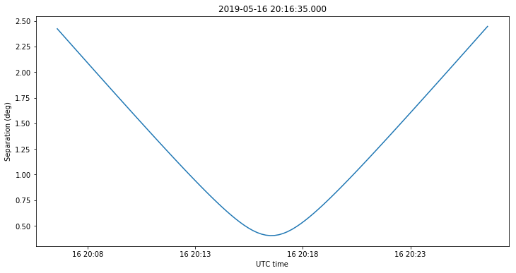
It turns out that each year the Moon passes roughly a dozen times in front of the dish beam. The next observation for me is on May 16. The separation in degrees between the centre of the Moon and the centre of the dish beam can be seen in the figure below.

This notebook can be used to plan for transits of other astronomical objects, but besides the Moon and the Sun, there are no other objects that are visible at 10GHz with a small dish. It is well known when the Sun passes in front of the beam, since this disturbs communications with GEO satellites. This is called Sun outage and it happens during a few days around the equinoxes (a few weeks sooner or later, depending on the latitude of the station). On the other hand, the transits of the Moon happen throughout the whole year, at rather unpredictable moments, so I think this notebook is quite useful to plan observations.

Rain fade in the QO-100 downlink

The Amateur transponders of Es’hail 2 have their downlink in the 10GHz Amateur band. Even though the path to the satellite through the atmosphere is rather short, in extreme weather conditions it is possible to observe a small amount of fading in the signal. Two days ago there was intense rain over Madrid. As I’m often recording the power of the narrowband transponder beacons and the transponder noise floor, I have examined my data to see if the effect of the rain is visible.

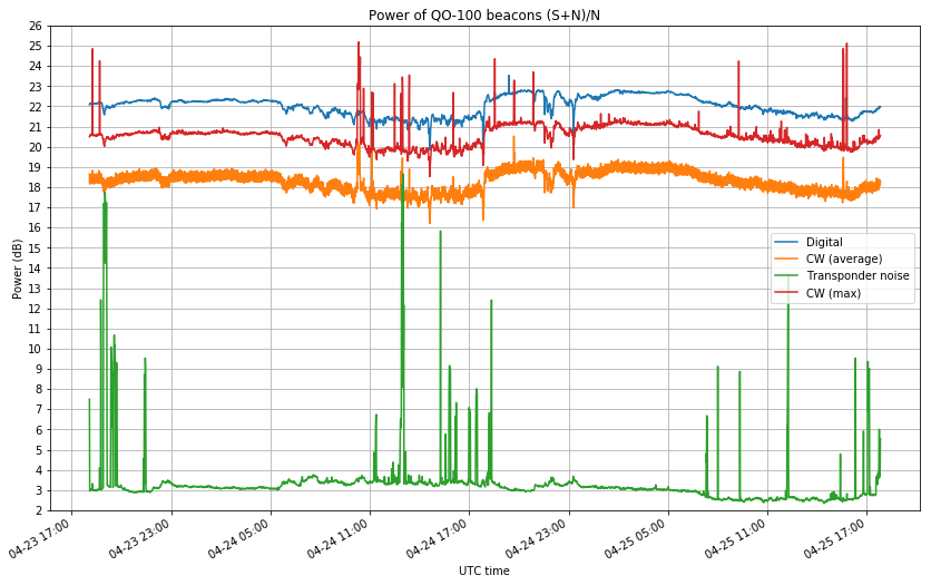
The data is plotted in the figure below. See this post for an explanation of the measurements.

The power of the beacons is not very stable. It can vary up to 2 or 3dB along the course of the day. Therefore, it is not so easy to measure the drop in signal power caused by rain. However, it is noticeable that on April 24, between 05:00 and 17:00 UTC, the power of the beacons varies much more rapidly than usually. A small ripple of 0.5dB of amplitude is visible on the data. I think that this ripple is caused by varying rain intensity. Therefore, the data seems to suggest that the rains two days ago caused up to 0.5dB of fading in the signal.

As seen from my station, the satellite is at an elevation of \(\theta = 33.6^\circ\), so assuming a slant factor of \(1/\sin \theta = 1.8\), so taking a typical height of around 1km for the column of rain (see the corresponding METAR for Madrid airport), we get an attenuation on the order of 0.3dB/km. However, all the measurements used here are too imprecise to obtain any good conclusions. See this related post, in which I measured a 2.5dB increase in the noise floor at 12GHz during a hailstorm, but no change in signal power.

QO-100 beacon FEC decoder

Since the BPSK beacon on the QO-100 narrowband transponder was first activated, I had thought that it only transmitted messages using the AO-40 uncoded protocol. However, a Twitter conversation a few days ago with Rob Janssen PE1CHL convinced me that FEC messages might be sent in between uncoded messages.

The AO-40 FEC protocol used a concatenated code with a (160, 128) Reed-Solomon code and an r=1/2, k=7 convolutional code, together with scrambling and interleaving to achieve very good performance. The same protocol has then been used in the FUNcube satellites, so I have an AO-40 FEC decoder in gr-satellites since I added support for AO-73.

It is quite easy to notice that the QO-100 beacon transmits both uncoded and FEC messages. Indeed, using my gr-satellites decoder, I see that an uncoded message is transmitted every 23 seconds approximately. Since an uncoded message comprises 514 bytes, it takes 10.28 seconds to transmit it at 400baud, so something else must be sent between uncoded messages.

A FEC message is formed by 5200 symbols (after applying FEC), so it takes 13 seconds to transmit at 400baud. This gives us the total 23.28 seconds that I had observed between uncoded messages. Note that the contents of the uncoded and FEC blocks are different. An uncoded block contains 8 lines of 64 characters plus 2 bytes of CRC. A FEC block only contains 4 lines of 64 characters, and no CRC.

I have added a FEC decoder to the QO-100 decoder in gr-satellites, so that it now decodes both FEC and uncoded messages.

Weekend maintenance to QO-100 NB beacons

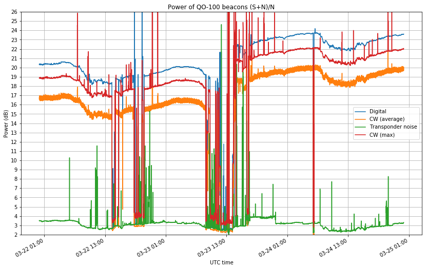
This weekend, the beacons of the Es’hail 2 narrowband transponder have undergone maintenance. The beacons have been off for several periods of a few hours on Friday and Saturday. After the maintenance, there are two main changes: the phase noise of the beacons has been fixed, and the beacons are now approximately 3dB stronger.

Since the opening of the transponder on February 14, some phase noise on the two beacon signals was appreciable slightly above the noise floor, and with the latest increase in power of the beacons, the phase noise was more evident. Now the problem is fixed and the transponder is clear of phase noise.

The figure below shows the power of the beacons and transponder noise (measured in 2kHz bandwidth). You can see that the beacon power has daily fluctuations of up to 2dB, but despite of this fact it is clear that the beacons are now approximately 3dB stronger than before (maybe even 4dB).

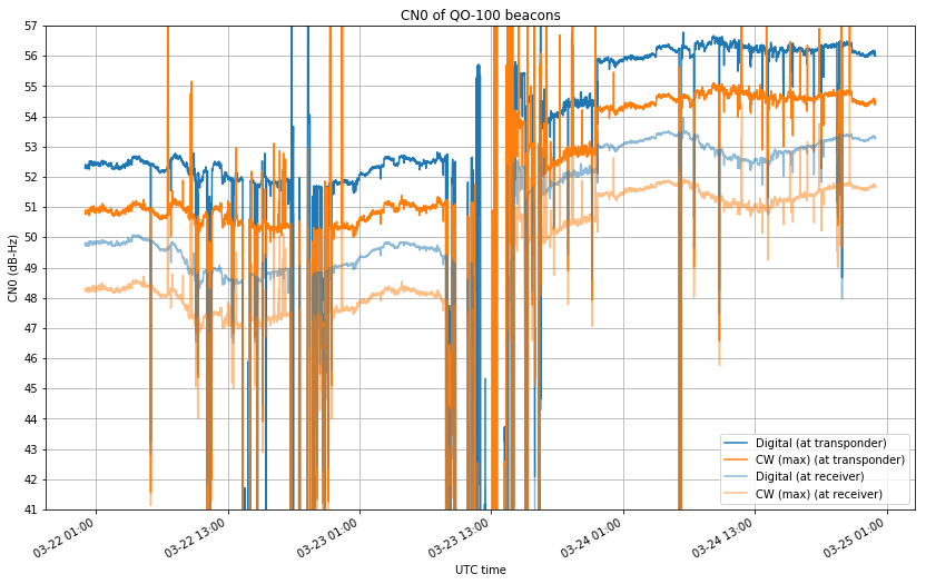
The figure below shows the CN0 of the beacons, measured both at the transponder and at my receiver (where it is lower due to system noise). The CN0 is now extremely high: 56dB for the BPSK beacon. In a previous post I thought about what could be done with 45dB of CN0. The conclusion was that if you want to fit a digital signal in an SSB channel bandwidth, you are much more bandwidth-limited than SNR-limited. This is now even more true.

With the increased beacon power, it should be fairly easy to decode the beacons with a bare LNB, even despite the fact that the transponder gain has been reduced twice. Also, now that the SNR of the beacons is so high, there is no excuse for being louder than the beacon. Anyone who is stronger than the beacon is most likely using too much power. Their mode of choice probably works equally well with several dB less of SNR.

Measuring QO-100 beacons frequency

Continuing with my frequency measurements of Es’hail 2, I have now been measuring the frequency of the beacons of the QO-100 narrowband transponder for several days. The main goal of these frequency measurements is to use Doppler to study the orbit of Es’hail 2. Previously, I had been doing frequency measurements on the engineering beacons at 10706MHz and 11205MHz. However, these beacons are currently being transmitted on a MENA beam, so I’m quite lucky to be in Spain, as they can’t be received in many other parts of Europe.

During the in-orbit tests of Es’hail 2, the engineering beacons were transmitted on a global beam, and I performed some differential Doppler studies with Jean Marc Momple 3B8DU, in Mauritius. The engineering beacons are no longer any good for these kind of studies, since their area of coverage is small. Thus, I have started to measure the beacons in the narrowband transponder, which covers all the satellite footprint.

Changes to the QO-100 NB transponder settings

Yesterday, AMSAT-DL announced that the narrowband transponder of QO-100 was under maintenance and that some changes to its settings would be made. This was also announced by the messages of the 400baud BPSK beacon. Not much information was given at first, but then they mentioned that the transponder gain was reduced by 6dB and a few hours later the beacon power was increased by 5dB.

Since I am currently doing continuous power measurements of the transponder noise and the beacons, when I arrived home I could examine the changes and determine using my measurements that the transponder gain was reduced by 5dB (not 6dB) at around 15:30 UTC, and then the uplink power of the beacons was increased by 5dB at around 21:00 UTC, thus bringing the beacons to the same downlink power as before. In what follows, I do a detailed analysis of my measurements.

New dish for Es’hail 2 reception

I have replaced the dish I had for receiving Es’hail 2 by a new one. The former dish was a 95cm offset from diesl.es which was a few years old. I had previously used this dish for portable experiments, and it had been lying on an open balcony for many months until I finally installed it in my garden, so it wasn’t in very good shape.

Comparing with other stations in Spain, I received less transponder noise from the narrowband transponder of QO-100 than other stations. Doing some tests, I found out that the dish was off focus. I could get an improvement of 4dB or so by placing the LNB a bit farther from the dish. This was probably caused by a few hits that the dish got while using it portable. Rather than trying to fix this by modifying the arm (as the LNB couldn’t be held in this position), I decided to buy a new dish.

Es’hail 2 frequency measurements

After being busy with other projects, I have resumed my frequency measurements of the Es’hail 2 beacons. The last measurement I performed was made when the satellite reached its operational slot at 26ºE. After manoeuvering to this spot, the Doppler was very small, on the order of 0.8ppb peak-to-peak, indicating a very accurate geostationary orbit. Now Es’hail 2 has been two months in its operational slot, inaugurating its Amateur transponders on February 14 and entering commercial service on March 7.

I am curious about studying again the Doppler at this point in the mission, to see how accurate the GEO orbit is. I am also interested in collaborating with other Amateurs to perform differential Doppler measurements, as I did with Jean Marc Momple 3B8DU. Here I detail the first results of my measurements.

QO-100 beacons power

In the QO-100 (Es’hail 2) narrow band transponder, the recommendation for the adjustment of your downlink signal power is not to be stronger than the beacon. This was also the recommended usage of the old AO-40. Since the transponder has two beacons marking the transponder edges: a CW beacon marking the lower edge and a 400baud BPSK beacon marking the upper edge, there has been some debate on Twitter about which beacon does this recommendation refer to and what does “stronger” mean.

Of course, more formally, signal strength means power, which is a well defined physical concept, so there should be no argument about what does power mean. However, there are two different power measurements used for RF: average power and peak envelope power. I will assume that the recommendation refers to average power, not to peak envelope power. This makes more sense from the point of view of the power budget of the satellite amplifier (The total average power it needs to deliver is just the sum of the average powers of the signals of all the users, while the behaviour of the peak envelope power is much more complicated).

Also, I think that using peak envelope power for this restriction would be a very strict requirement on high PAPR signals. Note that the PAPR of CW is 0dB and the PAPR of BPSK is between 2 and 3dB, depending on the pulse shaping, so these are rather low PAPRs. For comparison, a moderately compressed SSB voice signal has a PAPR of 6dB.

In my opinion, the main problem with these discussions about “signal strength” is that many people are trying to judge power by looking at their waterfall or spectrum display and seeing what signal looks “higher”. This kind of measurement is not any good, because it doesn’t take signal bandwidth into account, depends on the FFT size, the window function, etc. It doesn’t help that many popular SDR software don’t have a good signal meter displaying the average power of the signal tuned in the passband.

In any case, I was curious about whether the power of the two beacons is the same and whether there is any interesting change over time. I have made a GNU Radio flowgraph that measures the power of each of the two beacons and of the transponder noise, and saves them to a file for later analysis.