Concurso Costa del Sol V-UHF 2016

Yesterday, my father and I hiked to Cerro de San Pedro, SOTA summit EA4/MD-020 (1425m), to work QRP in this month’s national V-UHF contest: Concurso Costa del Sol. Since the forecast for Sunday was rainy, I decided to go up on Saturday’s afternoon. The summit is a short hike from a nearby road. We arrived to the summit around 14:25UTC, so I could work in the contest for a bit more than two hours until we started packing at 17:00UTC before it got too dark.

Activity seemed a little low, although this is not surprising, given that the national RTTY contest was also running at the same time. I also get the impression that there is more activity on Sunday mornings. Nevertheless, my results have been better than in March’s contest. I did fewer QSOs, but got more points and worked more DX. In fact, I could work almost everybody I heard. In the map below, as always, my location is marked in red, the stations in blue are those worked only in 144MHz and the ones in green where worked both in 144MHz and 432MHz.

Arduino LED driver: prototype finished

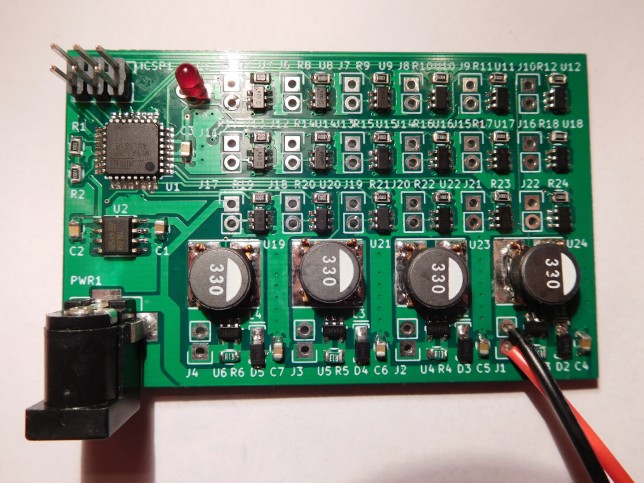
Today I’ve finished my prototype of the Arduino LED driver. I had already soldered and tested all the components quite a while ago, but I ran out of connectors for the LED strings, so I had to wait for more to arrive from China.

This project uses an Arduino-compatible ATmega328P and is able to drive up to 18 regular LED strings using the BCR420UW6 linear driver and 4 high-power LED strings using the AL8808 switching driver. The intended application is programmable lightning, such as Christmas or party lights.

PCB front
PCB front

Scanning Ku band satellites with the FUNCube Dongle

I’ve recently installed my satellite dish and modified LNBF in my garden. This equipment will be used to receive Es’hail 2, the first geostationary satellite carrying an amateur radio transponder. Here I’ll look at the hardware I’m using, how I did the alignment to the 25.5ºE geostationary orbital position where Es’hail 2 will be located, and how to have some fun scanning the direct broadcast satellites in the Ku band with a FUNCube Dongle Pro+.

Concurso Combinado V-UHF 2016

This weekend, being the first weekend in March, marks the start of the Spanish V-UHF contest season for this year. In previous years, I’ve been operating casually in some of these contests as a portable station. Sometimes I’ve worked on the countryside just outside my town, Tres Cantos, and on other occasions I’ve being enjoying the contest from a summit while doing a SOTA activation. My plan for this year is to participate in all (or almost all) of the contests and try to work from a summit as many times as I can. I pretend to work QRP (5 Watts) always and enter the 6-hour category, which allows working for a maximum of 6 consecutive hours.

Today, I’ve worked in the Concurso Combinado V-UHF. The weather forecast was too windy and cold to stay for several hours on a summit, so I decided to work from the countryside near town. I’ve worked this morning from 09:00UTC to 12:00UTC more or less. The equipment was, as usual, an FT-817ND and an Arrow satellite yagi antenna (3 elements on 144MHz and 7 elements on 432MHz). See below for a map of the stations worked. My position is marked in red, the stations worked in 144MHz only are marked in blue and the stations worked in both 144MHz and 432MHz are marked in green.

Building the OCXO/Si5351A kit from QRP Labs

Some posts ago, I spoke about the possibility of using the OCXO/Si5351A synth kit from QRP Labs as a low cost way of providing an external stable 27MHz reference to a satellite LNBF. I’ve received and built my kit some days ago, so here I will be looking at some aspects in the construction and performance of this kit.

Calibrating the S-meter in Linrad

In a previous post, I talked about the GALI-39 amplifier kit from Minikits. Here I will describe the procedure to calibrate the S-meter in Linrad (or another SDR) using this amplifier or any other amplifier with a known NF and an uncalibrated signal source. Leif Åsbrink has a youtube video where he speaks about the calibration of the S-meter in Linrad. However, he doesn’t use an amplifier, so I will be following a slightly different procedure.

Building the GALI-39 amplifier kit from Minikits

The GALI-39 is a DC-7GHz MMIC amplifier from Minicircuits. This device has a gain around 20dB and a NF of about 2.4dB. The nice thing about MMICs is that their input and output impedances are matched to 50Ω, so it’s quite easy to work with them. Minicircuits makes many MMIC amplifiers suiting different needs, but unfortunately their products are not so easy to get in small quantities.

Minikits.com.au is an Australian store that sells Minicircuits parts in small quantities as well as many interesting RF kits. I needed some RF amplifier having a known NF to do some signal level calibrations, so I ended up ordering the GALI-39 amplifier kit from Minikits. This kit includes just the GALI-39, a PCB and the handful of SMD components you need to bias the amplifier. At 22AUD, the price of the kit is about right and buying the kit instead of just the GALI-39 saves me to do the shopping for the assorted SMD components and using the PCB instead of botching some circuit is always nice, because the PCB uses microstrip transmission line (but the substrate is regular FR-4). Here I have a look at what is included in the kit (I’ve been unable to find a complete list on Minikit’s web).

An idea for a low cost stable 10GHz receiver

The satellite Es’Hail-2 is expected to be launched by the end of 2016. This will be the first geostationary satellite carrying an amateur radio transponder. As the launch date comes nearer, it becomes interesting to find a low cost solution to receive its 10GHz downlink.

Several amateurs have been experimenting with low cost LNBFs designed to receive satellite TV. These operate in the Ku band and usually cover the frequencies 10.7GHz-12.75GHz. However, many of these LNBFs have also good performance in the X band, and particularly in the amateur 10GHz band (10GHz-10.5GHz). In fact, the ASTRA-type LNBFs have a local oscillator which can be setted to either 9.75GHz or 10.6GHz. The 9.75GHz local oscillator mixes 10.386GHz (the narrowband terrestrial subband) to 618MHz, which is a frequency covered by most SDRs and conventional scanners. The satellite subband, which is 10.45GHz-10.5GHz gets mixed down to 700MHz-750MHz, a frequency which is also easy to deal with.

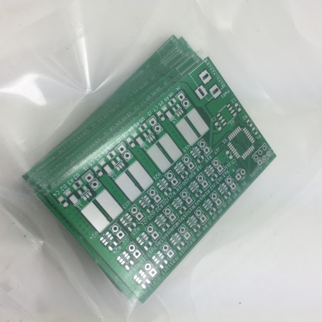
Arduino LED driver: PCBs shipped

This is a quick introduction to my Arduino LED driver project, since the PCBs for the prototype have being shipped from ShenZhen2U a couple of days ago. This project is fairly simple. The idea is to have an Arduino-compatible ATmega328P drive many LED strings, composed of one of the following two types of LEDs: regular or high-efficiency LEDs taking about 30mA, and high-power LEDs modules taking between 700mA and 1A. The applications I have in mind for this project are several lightning projects where a bunch of LEDs have to be controlled, perhaps in a complex way, but without needing much input (or none at all) from the outside world. Christmas and party lightning are good examples.

A total of 4 AL8808 switching mode LED drivers can be installed on the PCB to drive strings of high-power LEDs requiring up to 1A of current. To drive strings of regular LEDs, the BCR420UW6 linear mode LED driver is used. A total of 18 of these can be installed on the PCB. This is as much as you can control with the ATmega328P, as all of the output pins get used.

No USB is included in this project, since the idea is to program it via ISP. In case some interaction with the outside world is needed, the ISP header could be used to interface with SPI hardware. Everything runs off 12VDC which has to be provided by an external switching mode power supply.

PCB images
The PCB images provided by the manufacturer look quite nice

This is going to be open source hardware, so when I have actually built and tested the project I will post the schematics and PCB layouts to Github. Stay tuned for more information.

Estimation of the contribution of the frontend to the total noise figure

In a radio receiver composed of two stages, the total noise factor \(F\) can be computed using Friis’s formula as\[F = F_1 + \frac{F_2 – 1}{G_1},\]where \(F_1\) is the noise factor of the first block, \(G_1\) is the gain of the first stage and \(F_2\) is the noise factor of the second stage. If \(G_1\) is large enough, then the contribution of the second factor is small and the total noise factor of the whole system is essentially the same as the noise factor of the first stage. This is the reason why a low noise amplifier is useful as a frontend, because it has a low noise factor \(F_1\) and high gain \(G_1\).

If \(F_2\) and \(G_1\) are known (perhaps only approximately), then it is easy to check if the contribution of the frontend to the total noise figure is large enough so that the total noise figure is determined by the noise figure such frontend alone. However, it may happen that one or both of \(F_2\) and \(G_1\) are not known. In email communication, Leif Åsbrink mentioned that there is an easy way of checking the contribution of the frontend without knowing these parameters. The method is to switch off the frontend and note the drop in the noise floor. He gave the following estimates: if the noise floor drops by more than 10dB, then the total noise figure is the same as the noise figure of the frontend up to 1dB; if the noise floor drops by more than 17dB, then the total noise figure is the same as the noise figure of the frontend up to 0.1dB. Here I present the maths behind these kind of estimates.