I’m happy to announce the release of Maia SDR, an open-source FPGA-based SDR project focusing on the ADALM Pluto. The first release provides a firmware image for the Pluto with the following functionality:
Web-based interface that can be accessed from a smartphone, PC or other device.
Real-time waterfall display supporting up to 61.44 Msps (limit given by the AD936x RFIC of the Pluto).
IQ recording in SigMF format, at up to 61.44 Msps and with a 400 MiB maximum data size (limit given by the Pluto RAM size). Recordings can be downloaded to a smartphone or other device.
BlueWalker 3 is a satellite built by AST SpaceMobile that was launched in 2022-09-11. It is as a prototype mission that will try to communicate from low Earth orbit with unmodified cellphones on ground using a large 64 m² unfoldable phased array antenna. It has received some criticism because of concerns of the satellite being too bright due to the large antenna (impacting astronomy observations) and potentially causing RF interference to radioastronomy and other services, since the cellular bands it will use are normally used only in terrestrial applications.
It also received criticism when shortly after launch, amateur radio operators noticed that the satellite was transmitting packets on 437.500 MHz, in the UHF amateur satellite band. The mission of this satellite is not compatible with the amateur radio service and it hasn’t received IARU coordination. There were some arguments on Twitter about whether BlueWalker 3 actually had the proper experimental license from the FCC to do this or not, and people posted ITU SNL filings and FCC applications. I didn’t track all of this in detail, so I don’t have a well informed opinion about whether BlueWalker 3 is following the regulations correctly.
A month ago, I looked at the UHF packets and checked that BlueWalker 3 used exactly the same modulation and coding as Light-1, which is a 3U cubesat from United Arab Emirates (this was first discovered by Tetsurou Satou JA0CAW). The framing contains the typical elements of the built-in packet handler of low cost FSK chips such as the Texas Instruments CC11xx family. Scott Tilleynoticed some details that seem to explain this connection: Light-1 was built by NanoAvionics, which apparently has collaborated with AST SpaceMobile in the BlueWalker 3 mission. Therefore, it seems that the satellite bus used by BlueWalker 3 is that of a typical cubesat.
In my previous post I wrote about the protocols used by Blockstream Satellite. This was motivated by a challenge in GRCon22’s CTF. In that challenge, muad’dib sent the flag as a Blockstream API message and recorded the Blockstream Satellite DVB-S2 downlink as the message was broadcast. The recording was used as the IQ file for the challenge.
In my post, I gave a look at how all the protocol stack for the Blockstream API works: DVB-S2, MPE, IPv4, UDP, plus a custom protocol that supports fragmentation and application-level FEC. However, I didn’t give any details about how the protocols used to broadcast the Bitcoin blockchain work. This runs on another UDP port, independently of the Blockstream API. At that time I didn’t understand much about it, even though during the CTF I was trying to search for the flag in a Bitcoin transaction and looking at the source code of bitcoinsatellite to try to figure out how it worked.
After my previous post, Igor Freirecommented some details of the FEC used in bitcoinsatellite. This is quite interesting by itself. Two FEC libraries by Chris Taylor are used: the Wirehair O(N) fountain code for larger blocks, and the CM256 MDS code based on Cauchy matrices over GF(256) (this is very similar to Reed-Solomon used as erasure coding). This motivated me to continue studying how all this works.
Now I have been able decode the Bitcoin transactions in the CTF recording. These don’t use any FEC, since transactions are small. I believe that there aren’t any blocks fully contained in the 35 second recording, so to see how the FEC codes work (which could be quite interesting) I would need a longer recording.
In this post I’ll show how to decode the Bitcoin transaction in Blockstream Satellite. The materials can be found in this repository.
A heighliner just passed through “folded space” and it has sent a secret message to the remaining members of House Atreides on the surface of Arrakis. The communication protocol was historically used for sending visual propaganda films and archival files, recently however, Duke Leto had his engineering guild repurpose the transmission unit for financial transactions. It’s the perfect place for a covert message, the Harkonnens would never think to look there… The original transmission was on Frequency 12.0164GHz. Our groundstation receiver downconverted to 1.2664GHz.
Heighliner challenge description
I didn’t manage to solve this challenge, mainly because I was looking in the wrong place. I was focused on looking at the Bitcoin blockchain chunks, but the flag was in a Blockstream Satellite API message, and I wasn’t aware of the existence of API messages back then. After the CTF ended, a few of us were discussing this challenge in the chat. None of us really understood all the details about how the Blockstream Satellite system works. Since the intended way of solving the challenge was setting up and running the Blockstream Satellite receiver tools, an in-depth understanding wasn’t really necessary.
I have some interest in satellite filecasting systems since I reverse-engineered Outernet back in 2016, so I’ve been taking some time after the CTF to look at the details of how Blockstream Satellite works. While attempting to solve the challenge, I found that detailed enough documentation wasn’t available. There is some high-level documentation, but for the details you need to go to the source code (which is a typical situation).
In this post I describe the details of how Blockstream Satellite works, using the recording from the CTF challenge as an example. I will mainly focus on the Blockstream Satellite API, since I haven’t been able to understand all the details of the Bitcoin blockchain FEC blocks.
I have a couple of ideas in mind that involve connecting an ADALM-Pluto SDR to a phone or tablet. Usually, the Pluto is connected to a PC through USB, and the Pluto acts as an Ethernet device, so that network communications between the PC and Pluto are possible. I want to have the same thing running with my Android phone, which is an unrooted Xiaomi Mi 11 Lite (model M2101K9AG, if anyone is curious).
As usual when trying to do something slightly advanced with Android, this hasn’t worked on the first go, so I’ve spent some time debugging the problem. Long story short, in the end, the only thing I need to make this work is to run
on the Pluto once and reboot (these settings are saved as uBoot environment variables to persistent storage), then enable Ethernet tethering on the phone every time that I connect the Pluto. I can go to the web browser in the phone and check that I can access the Pluto web server at 192.168.89.1.
ADALM-Pluto web server browsed from Android
Hopefully the rest of this post will give useful information about how everything works behind the scenes, as your mileage may vary with other Android devices (or if you try with an iOS device, of which I know next to nothing).
I haven’t seen many people doing this, so the documentation is scarce. PABR did a set up with LeanTRX, the Pluto and an Android phone, but they were running the Pluto in host mode and the Android phone in device mode, and I’m doing the opposite. Note that when you connect a Pluto and phone together, the roles they take will depend on the USB cable. My phone has USB-C, so I’m using a USB-C plug to type-A receptacle cable (USB-C OTG cable) together with the usual USB type-A plug to USB micro-B plug cable (the cable provided with the Pluto). There is also this thread in the ADI forums, but it doesn’t really say anything about Ethernet over USB.
Satellite RF signals are shifted in frequency proportionally to the line-of-sight velocity between the satellite and groundstation, due to the Doppler effect. The Doppler frequency depends on time, on the location of the groundstation, and on the orbit of the satellite, as well as on the carrier frequency. In satellite communications, it is common to correct for the Doppler present in the downlink signals before processing them. It is also common to correct for the uplink Doppler before transmitting an uplink signal, so that the satellite receiver sees a constant frequency.
For Earth satellites, these kinds of corrections can be done in GNU Radio using the gr-gpredict-doppler out-of-tree module and Gpredict (see this old post). In this method, Gpredict calculates the current Doppler frequency and sends it to gr-gpredict-doppler, which updates a variable in the GNU Radio flowgraph that controls the Doppler correction (for instance by changing the frequency of a Frequency Xlating FIR Filter or Signal Source).
I’m more interested in non Earth orbiting satellites, for which Gpredict, which uses TLEs, doesn’t work. I want to perform Doppler correction using data from NASA HORIZONS or computed with GMAT. To do this, I have added a new Doppler Correction C++ block to gr-satellites. This block reads a text file that lists Doppler frequency versus time, and uses that to perform the Doppler correction. In this post, I describe how the block works.
This post is a continuation of my series about LTE signal analysis. In the previous post I showed how to decode the PHICH. Now we will decode two other downlink channels, the PBCH (physical broadcast channel) and the PDDCH (physical downlink control channel).
The PBCH is used to transmit the MIB (master information block). This is a small data packet that all the UEs must decode after detecting a cell using the synchronization signals. The MIB contains essential information for the usage of the cell, such as the cell bandwidth and PHICH configuration. The PDDCH contains control information, such as uplink grants and the scheduling of the PDSCH (physical downlink shared channel).
The PBCH and PDDCH use the same kind of channel coding: a tail-biting k=7, r=1/3 convolutional code with a circular buffer for rate matching that performs puncturing and repetition coding as needed to obtain the required codeword size. The remaining aspects of the PBCH and PDDCH are quite different, so they will be treated separately.
As usual, we will be using a short IQ recording from my local cell site. The link to the recording is given at the end of the post.
This is a continuation of my series of posts about LTE. In the previous post we looked at the downlink cell-specific reference signals (CRS), transmit diversity equalization, and the demodulation of the PBCH (physical broadcast channel), PCFICH (physical control format indicator channel) and PDSCH (physical downlink shared channel). In this post we will look at the PHICH (physical hybrid ARQ indicator channel). As usual, I will be analysing the recording of a base station that I did in the first post about the LTE downlink.
The PHICH is used to send hybrid-ARQ ACK/NACKs to the UEs. Each PHICH transmission carries a single bit, either ACK (encoded by the bit 1) or NACK (encoded by the bit 0). Repetition encoding is used to increase the chances of correct decoding, and an orthogonal overlay code allows transmitting information for several UEs using the same resource elements.
The PHICH is transmitted in the control region of the subframe, which is formed by the first 1, 2, or 3 symbols of the subframe (according to the CFI value). As other control channels, the PHICH uses REGs. Recall that a REG is a set of 4 resource elements which are not used for the transmission of the CRS and which are adjacent in frequency if we ignore the resource elements used for the CRS. For instance, when 2 or 4 antenna ports are used for the CRS, in the first symbol of the subframe two resource elements in every block of 6 are used for the CRS. The other 4 resource elements form a REG. Therefore, there are 2 REGs per resource block. In symbols 2 and 3 there may not be resource elements allocated to the CRS, so there are 3 REGs per resource block in that case.
A PHICH transmission uses 3 REGs which are equally spaced over the bandwidth of the cell, in order to give frequency diversity. This is similar to the PCFICH, which uses 4 equally spaced REGs in the first symbol of the subframe. Depending on the configuration of a parameter called PHICH duration, the PHICH can either use the first symbol in each subframe (normal PHICH duration), or the first 2 or 3 symbols in each subframe (extended PHICH duration). Here we will only look at the normal PHICH duration, which is what is used in the recording. In the normal duration, the 3 REGs are transmitted simultaneously in the first symbol of the subframe. In the extended duration the 3 REGs are distributed over the first 2 or 3 symbols of the subframe.
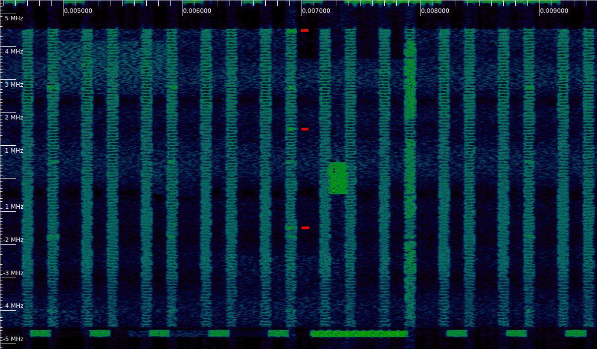
In the waterfall below we can see a PHICH transmission. In the first symbol of each subframe we can see the 4 REGs used by the PCFICH (the lower frequency REG, at around -4 MHz is barely visible). In the subframe near the centre of the image (which incidentally contains the synchronization signals), in addition to these 4 REGs, there are 3 more REGs in use, which I have marked with red ticks. These form a PHICH transmission.
Waterfall of an LTE downlink signal, showing PHICH transmissions
In my previous post I showed a GNU Radio demodulator for the QO-100 multimedia beacon, which AMSAT-DL has recently started to broadcast through the QO-100 NB transponder, using a downlink frequency of 10489.995 MHz. This demodulator flowgraph could receive and save to disk the files transmitted by the beacon using the file receiver from gr-satellites. However, the performance was not so good, because it had a couple of ad-hoc Python blocks. Also, the real-time streaming data (which uses WebSockets) was not handled.
I have continued working in the decoder and solved these problems. Now we have a decoder with good performance that uses new C++ blocks that I have added to gr-satellites, and the streaming data is supported. I think that the only feature that isn’t supported yet is displaying the AMSAT bulletins in the qo100info.html web page (but the bulletins are received and saved to disk).
I have added the decoder and related tools to the examples folder of gr-satellites, so that other people can set this up more easily. In this post I summarise this work.
Last weekend, AMSAT-DL started some test transmissions of a high-speed multimedia beacon through the QO-100 NB transponder. The beacon uses the high-speed modem by Kurt Moraw DJ0ABR. It is called “high-speed” because the idea is to fit several kbps of data within the typical 2.7 kHz bandwidth of an SSB channel. The modem waveform is 2.4 kbaud 8APSK with Reed-Solomon (255, 223) frames. The net data rate (taking into account FEC and syncword overhead) is about 6.2 kbps.
I had never worked with this modem before, even though it served me as motivation for my 32APSK modem (still a work in progress). With a 24/7 continuous transmission on QO-100, now it was the perfect time to play with the modem, so I quickly put something together in GNU Radio. In this post I explain how my prototype decoder works and what remains to be improved.