As you may know, I am on a scientific expedition in Antarctica until mid-February. Currently I am in the Spanish base Gabriel de Castilla, where we have relatively good satellite internet access. As I have some free time here, I have updated the DSLWP-B camera planning to reflect the upcoming observations announced by Wei Mingchuan BG2BHC on 2019-02-03 14:30 and 2019-02-04 08:20.
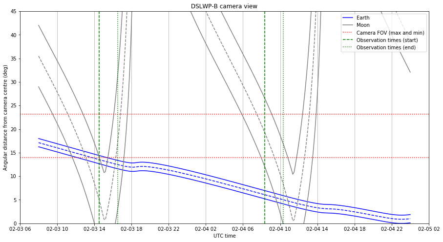
As we can see in the figure below, the Earth will be very near to the centre of the image, since there is a new Moon on February 4 (recall that the DSLWP-B camera points away from the Sun, so the Earth is visible on the camera when there is a new Moon, as the Earth is then opposite to the Sun, as seen from the Moon).
The observation times have been selected taking into account the orbit around the Moon, so that the Moon is also visible on the image. On February 3 the Moon should be completely visible inside the camera field of view. On the contrary, on February 4, the Moon will only be partially visible inside the frame.
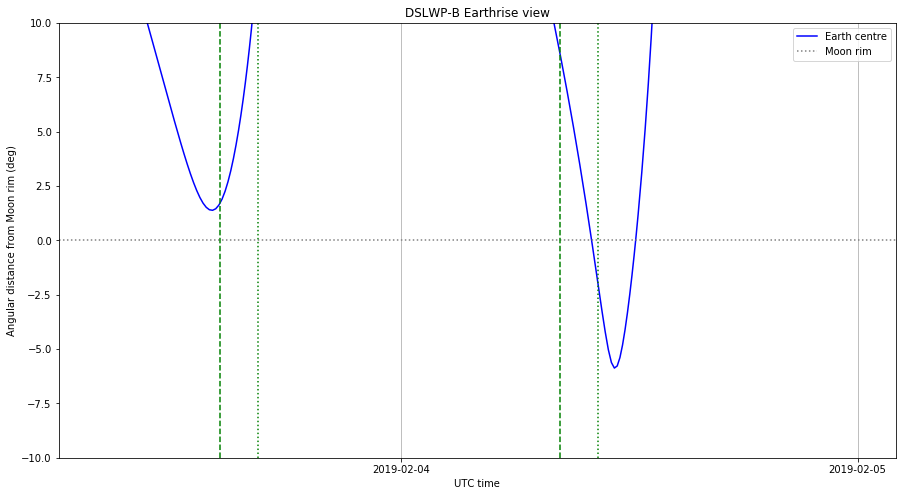
The figure below shows the angular distance between the centre of the Earth and the rim of the Moon. This kind of graph can be used to compute the times when the Earth crosses the Moon rim, allowing us to take an “Earthrise” image. There is an Earthrise event on February 4, during the time when the Amateur payload is active. Generally, an image is taken whenever the Amateur payload powers up, but in this case it could be possible to command the payload manually to take an image near the Earthrise event.
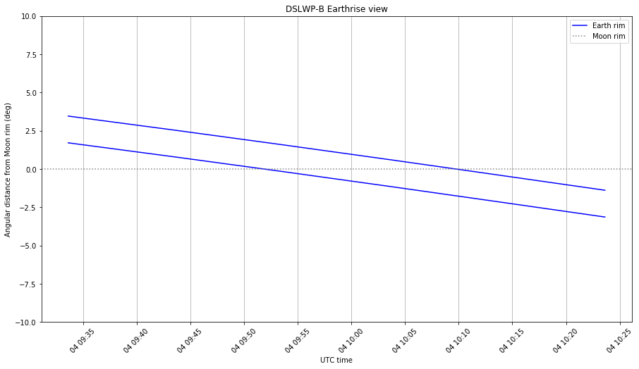
The figure below shows in detail the Earthrise event, with both edges of the Earth plotted. It seems that a good time to take the Earthrise image is on 2019-02-04 10:00 UTC.