I have being receiving several 10GHz on different WebSDRs with linrad to get a rough idea of the performance of the beacons and receivers, both in terms of frequency stability and phase noise. Here are the results.
Posts
Phase noise of 27MHz references for a Ku-band LNBF
Today, I’ve being measuring the phase noise of the different 27MHz references that I have for my Ku-band LNBF. The LNBF is an Avenger PLL321S-2. I’ve modified it, removing the 27MHz crystal and including a connector for an external 27MHz reference signal. In my lab, I have the following equipment to generate a 27MHz signal:
- OCXO/Si5351A kit. This kit includes a 27MHz OCXO and a Si5351A frequency synthesizer. The Si5351A can act as a buffer and output the OCXO signal directly or generate a 27MHz clock.
- A DF9NP 27MHz PLL and a DF9NP GPSDO. The GPSDO generates a 10MHz signal which is locked to GPS. The PLL generates a 27MHz from the 10MHz signal.
I’ve used linrad to receive the beacon of BADR-5 at 11966.2MHz using different references for the 27MHz signal. The AFC in linrad tries to compensate for any drift in the reference or the satellite beacon. By averaging, one can get good plots of the sideband noise of the beacon. This is far from a proper lab test, but it gives a good idea of the performance of the references.
Concurso Atlántico V-UHF
Today, I’ve participated in this month’s national V-UHF from Cerro de San Pedro, SOTA summit EA4/MD-020 (1425m). I arrived the summit a bit before 10:00UTC and worked until the end of the contest (14:00UTC). The equipment was the usual: a Yaesu FT-817ND and an Arrow satellite yagi antenna (3 elements in 144MHz and 7 elements in 432MHz).
Find below the map of stations worked. My location is in red, stations worked both in 144MHz and 432MHz are in green and stations worked only in 144MHz are in blue.
Using the CC1101 and Beaglebone black for IP traffic on 70cm
Lately, I have been experimenting with using a CC1101 chip together with a Beaglebone black single board ARM computer to transmit IP traffic over the 70cm Amateur band. There has been a similar project from OEVSV, but I’ve never seen this project reach a final form. Edouard F4EXB has some code that uses the Raspberry Pi instead. Presumably, this will suffer from problems when using the higher data rates supported by the CC1101, as his software is not real-time.
The goal of my project is to build an affordable 70cm IP transceiver with a power of a few Watts. This can be used in the Hamnet Amateur Radio IP network. The modulation should not use more than a couple of hundreds of kHz’s of spectrum, as it doesn’t seem very sensible to take up much more spectrum in the 70cm band. Although the usual maximum bandwidth in the 70cm band is 20kHz, the IARU R1 bandplan allows for wideband experiments around 434.000MHz. A data rate of 128kbps with MSK modulation seems about right, as it uses roughly 200kHz of spectrum. Further on-the-air tests will perhaps change these parameters a bit.
KISS, HDLC, AX.25 and friends
A while ago, I uploaded my gr-kiss out-of-tree GNUradio module to Github. This is a set of blocks to handle KISS, HDLC and AX.25, which are the protocols used in amateur packet radio. There are several other OOT modules that do similar things, but I didn’t like the functionality of them very much. While programming this module, I’ve also noted that the documentation for these protocols is not so good sometimes. Here I’ll give a brief description of the protocols and explain how everything works together.
Concurso Sant-Sadurní V-UHF
Last Sunday, I hiked up Cerro de San Pedro, SOTA summit EA4/MD-020 (1425m) to work in this month’s national V-UHF contest. I was on the summit for 4 hours, from 7:00UTC to 11:00UTC, and I managed to work quite a few stations. As always, I used my portable QRP station consisting of a Yaesu FT-817ND and an Arrow satellite yagi antenna (3 elements in 144MHz and 7 elements in 432MHz).
In the map of stations worked, my position is in red, stations worked both in 144MHz and 432MHz are in green and stations worked only in 144MHz are in blue.
Trying to decode data from ÑuSat
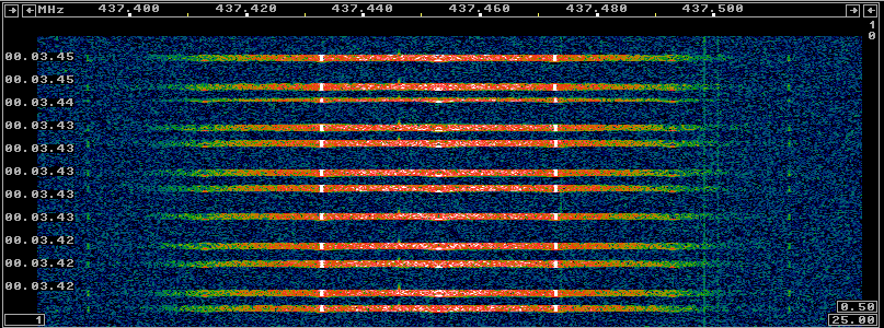
Last Monday, a Chinese CZ-4B rocket launched the Chinese Earth observation satellite ZY-3 and the Argentinian satellites ÑuSat-1 and 2. These two satellites are the first of the Aleph-1 constellation of Earth observation satellites. ÑuSat-1 carries LUSEX, an Amateur payload which consists of a U/V linear transponder. Also, the two ÑuSat satellites transmit backup telemetry in the 70cm Amateur band, as one can see in the IARU frequency coordination application. In fact, the latest news is that ÑuSat-1 transmits telemetry on 436.445MHz and ÑuSat-2 uses 437.445MHz. According to the public announcements, the telemetry was supposed to be 9200 baud or 19200 baud. However, some people have noticed that, on the contrary, it is 40 kbaud. Although the modulation and coding specifications are not public, I’ve taken a look at an IQ recording of ÑuSat-2 by Mike DK3WN to see if I can decode anything. Here are my findings.
GOMX-3 data download
This weekend, Mike DK3WN caught GOMX-3 downloading a good amount of data. See his post here. This data consists mainly of the satellite retransmitting a lot of beacons that were generated during the last 16 hours or so.
GomSpace has recently released a complete parser for GOMX-3 beacons of type 1 0 (these are the beacons that contain ADS-B data). I have already incorporated this code into my gr-ax100 fork.
The binary data in KISS format (almost 250KB) and the parsed beacon data received during this data download is in gist. Probably the most interesting thing is the ADS-B data. Below you can see all the aircraft on the map. Clicking on any of them will show the details for that aircraft.
Since the orbit of GOMX-3 has an inclination of 51.6º, the satellite doesn’t usually detect aircraft above 55ºN or below 55ºS. GomSpace has an image which shows lots of flights received with GOMX-3. There, the major air routes and hubs are apparent.
LilacSat-2 subaudio telemetry
Yesterday, the FM repeater on the Amateur satellite LilacSat-2 was active. I’ve talked about LilacSat-2 before, but so far I hadn’t made any recordings containing subaudio telemetry. While contacting several Spanish stations (EA5TT, EA1JM and EA1IW) throughout the pass, I made an IQ recording to analyse the telemetry later. Here I take a look at the telemetry format and the decoded data.
Scramblers and their implementation in GNU Radio
A scrambler is a function that is applied to a sequence of data before transmitting with the goal of making this data more “random-like”. For instance, scrambling avoids long runs of the bits 0 or 1 only, which may make the receiver loose synchronization or cause spectral concentration of the signal. The receiver applies the inverse function, which is called descrambler, to recover the original data. The documentation for the scrambler blocks in GNU Radio is not very good and one may need to take a look at the implementation of these blocks to get their parameters right. Here, I’ll try to explain a bit of the mathematics behind scramblers and the peculiarities of their implementation in GNU Radio.


