Some days ago, Hans Hartfuss DL2MDQ sent me an email about some frequency measurements of the QO-100 NB transponder BPSK beacon that he had been doing. The BPSK beacon is uplinked from Bochum (Germany) through the transponder, and as the beacon is generated using a very good Z3081A GPSDO as a reference, the frequency drift observed on the beacon downlink is caused by Doppler and the drift of the local oscillator of the transponder.
In his measurements, Hans observed some small oscillations or “wiggles” that didn’t seem to be caused by Doppler. Decided to investigate this, I started to do some measurements of my own. This post is an account of my measurements and findings so far.
To perform the measurements, I’m using as a reference the Vectron MD-011 GPSDO development kit that Carlos Cabezas EB4FBZ has lent me. I already used this GPSDO to perform some measurements of the short term Allan deviation of the transponder LO. The Vectron gives a 10MHz output which drives a DF9NP 27MHz PLL. The output of this PLL is used as a clock for the LNB (an Avenger PLL321S-2) and the LimeSDR mini (as indicated here).
To measure the frequency of the BPSK beacon, I use GNU Radio. A Costas loop with a bandwidth of 1Hz is used to lock the beacon, and phase measurements from this Costas loop are stored in a file at a rate of 100Hz for later processing. The flowgraph can be obtained here.
The average frequency in a particular observation interval can be computed simply by unwrapping the phase measurements in this interval and subtracting the final phase minus the initial phase. To study the measurements, I am using an averaging period of 10 seconds, which already reduces the noise enough to be able to see fine detail. The calculations are done in this Jupyter notebook.
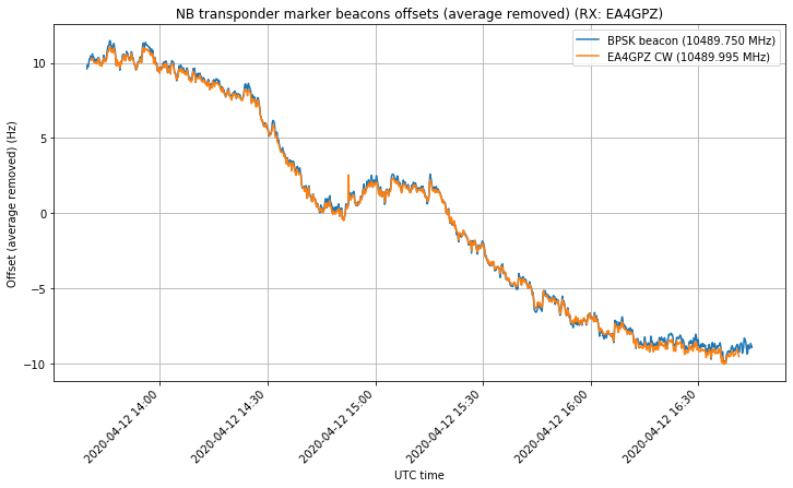
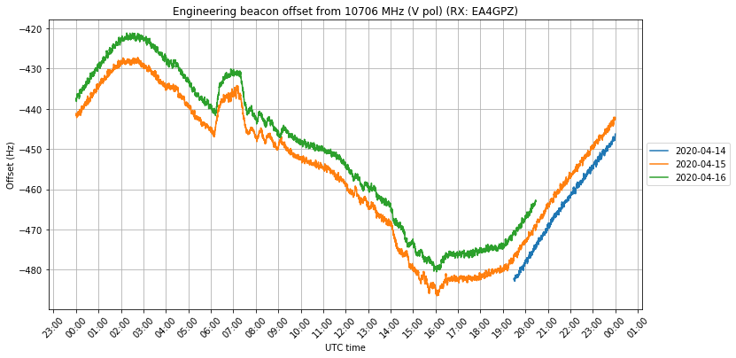
The time series of frequency measurements can be seen in the figure below. The gap at the beginning of 2020-04-11 was caused by a network problem causing data loss overnight, while on 2020-04-15 and 16 I switched the system to observe the engineering beacon at 10706MHz, as I will explain below.
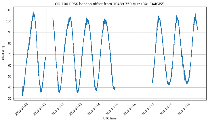
The daily sinusoidal curve is the characteristic Doppler curve of a GEO satellite. It is caused by the orbit not being perfectly circular and not having an inclination of exactly zero degrees. These two factors make the satellite move with respect to ground-based observers during the course of a revolution (a sidereal day), causing the sinusoidal curve.
The nominal downlink frequency of the beacon is 10489.750MHz. It is uplinked at a nominal frequency of 2400.250MHz and the transponder local oscillator has a nominal frequency of 8089.5MHz. We see that the Doppler curve has an offset of approximately 75Hz with respect to the nominal frequency due to a series of factors: transponder LO offset, errors due to fractional-N synthesis in the uplink system, and errors due to fractional-N synthesis in my receive system.
The figure below shows the measurements according to the time of day. We already see some wiggles that happen every day between approximately 22:00 and 06:00 UTC, and 11:00 and 16:00 UTC.
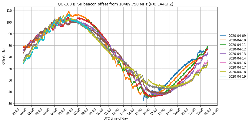
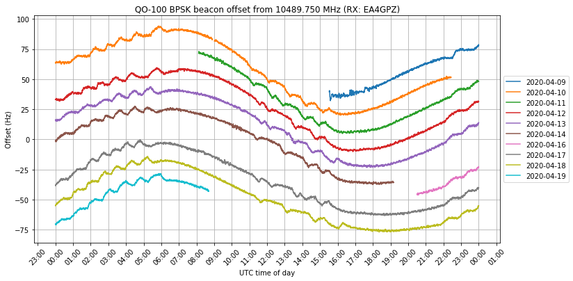
The wiggles can be seen better if we add an artificial offset of -15Hz per day to each of the curves in order to prevent them from overlapping. The wiggles happen every day in more or less the same time windows, and have roughly the same shape. It seems that the windows happen slightly sooner every day, though this is not completely clear, as it is not easy to determine precisely the moment at which the wiggles start. Indeed, it might seem that in 9 days the window has moved half an hour, which would indicate that the period with which the wiggle windows repeat is a sidereal day.
I have been in contact with Mario Lorenz DL5MLO from AMSAT-DL regarding this study, and he told me that the GPSDO at Bochum should not be trusted completely. Apparently they are seeing that the GPSDO is reporting an EFC error, which means that it is at the OCXO control voltage limit. Due to the lockdown for COVID-19, the AMSAT-DL engineers can’t access the Bochum groundstation to take a closer look at the problem.
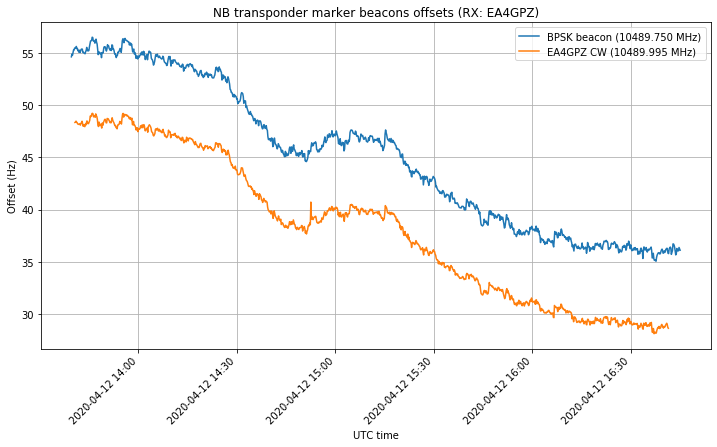
To validate that the uplink isn’t causing any problems, during a couple hours I transmitted a CW carrier through the NB transponder with my station. Using GNU Radio, a PLL with a bandwidth of 1Hz was used to lock the downlink of this carrier and output phase measurements at a rate of 100Hz as in the case of the BPSK beacon. The measurements of the downlink frequencies of this tone and of the BPSK beacon were done simultaneously, but not in a synchronized manner (i.e., running in independent flowgraphs). The flowgraph I used is here.
A downlink frequency of 10489.995MHz, near the upper edge of the transponder was selected as downlink frequency for this CW carrier, and a weaker Morse signal with my callsign was transmitted continuously 500Hz below the main CW carrier to comply with signal identification requirements.
The measurements are shown in the figure below. The offset of approximately 7Hz between the BPSK beacon and CW carrier is due to errors in fractional-N synthesis both in the uplink at Bochum and in my own uplink.
By subtracting the average on each of these time series, we get the figure below, where we can see that both measurements coincide almost exactly. Moreover, we can clearly see that the wiggles happen in both signals. This means that the BPSK beacon uplink is probably correctly locked to GPS (or its holdover is really good), and that the wiggles aren’t an effect caused by the BPSK beacon uplink.
Jean Marc Momple 3B8DU has been kind enough to help me with the measurements and has made a 30 hour recording of the BPSK beacon with his station in Mauritius. I have processed it with this GRC file. Since Mauritius is quite distant from Spain, the Doppler curves seen in Spain and Mauritius are different, and the movement of the satellite can be studied by differential Doppler measurements, as I showed in this post. These cancel out the transponder local oscillator drift, as it is common to both stations.
The figure below shows the comparison of the data measured by Jean Marc in blue and the data measured by me in orange. I don’t know why the Doppler curve measured by Jean Marc is centred at roughly -45Hz, while mine is centred at approximately 65Hz. This is a large difference of 110Hz that ought to be due to errors in the fractional-N synthesis of our receivers. I guess that most SDRs have an error much smaller than this, so the main contributor to the error are probably the LNBs. I have shifted down my Doppler curve to line it up with Jean Marc’s.
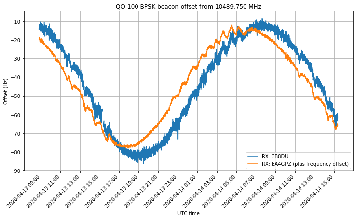
We can see that Jean Marc’s curve is more noisy than mine, since he is using a less stable BG7TBL GPSDO. The Doppler curves are slightly different, as normal, but the same wiggles are present in both curves. To see this more in detail, I have subtracted the two Doppler curves. The result is shown in blue in the figure below. I have also included my Doppler measurement in grey as a reference to show where the wiggles are present. We can see that there are no wiggles in the blue curve.
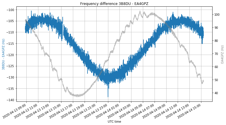
This means that the wiggles are common to the observation in both stations. This shows that it is extremely likely that the cause of the wiggles is the transponder local oscillator. It also provides strong evidence against the idea that the wiggles are produced by spacecraft movement.
The differential Doppler observation is sensitive only to spacecraft movement in the direction parallel to the baseline joining Mauritius and Madrid (which is roughly a northwest-southeast direction). Therefore for some spacecraft movement not to produce any effect in the differential Doppler observation, the movement should happen in the plane perpendicular to this baseline. It seems very unlikely that if the wiggles were caused by spacecraft movement, this movement was also aligned with respect to Mauritius and Madrid in this particular manner.
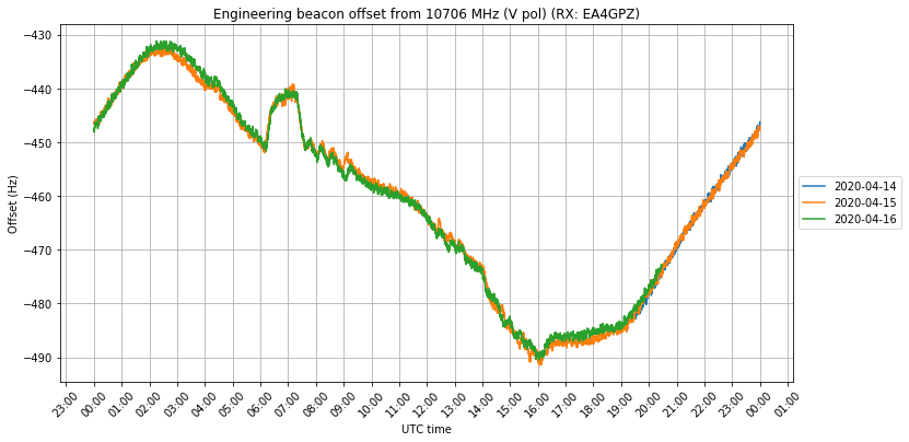
In order to try to gather more information about the wiggles, I observed the engineering beacon on 10706MHz for two days. This is one of the two beacons of Es’hail 2 and it doesn’t form part of the Amateur radio payload. Back when Es’hail 2 was launched, I did a series of posts studying the Doppler of the engineering beacon. It seems that during the in-orbit test phase this beacon was transmitted on a global RHCP beam, but at some point after that it switched to a local beam so it can’t be received in most of the world. Fortunately, the beacon is strong in Madrid, as it is not too far off the coverage of the MENA (middle-east and north Africa) area. However, it can’t be received in most of Europe nor in Mauritius, so it is difficult to contrast my measurements with other people.
The engineering beacon was measured in the same way that I measured the CW tone I put through the transponder, using a PLL with a 1Hz bandwidth. The measurements can be seen in the figure below. The beacon is some 460Hz low, but this is normal and done by design, to prevent different satellites transmitting beacons at 10706MHz to line up exactly on the same frequency. We see a daily pattern, but it doesn’t look very sinusoidal, and there is a weird thing happening at 6:00 UTC on both days.
If we plot the curve by day, we see that the same behaviour repeats almost exactly every day.
For clarity, we can offset each of the days by 5Hz to prevent them from overlapping, obtaining the figure below.
In the figure below I compare the curves followed by the engineering beacon and the BPSK beacon. I have subtracted the average to each of the curves and then subtracted an additional 7Hz offset to the engineering beacon to try to line it up with the sinusoid followed by the BPSK beacon between 17:00 and 02:00 UTC, where it seems to follow a sinusoidal behaviour. What happens between 02:00 and 17:00 UTC is a mystery to me, as the curve deviates greatly from the sinusoidal that would be caused by Doppler alone.
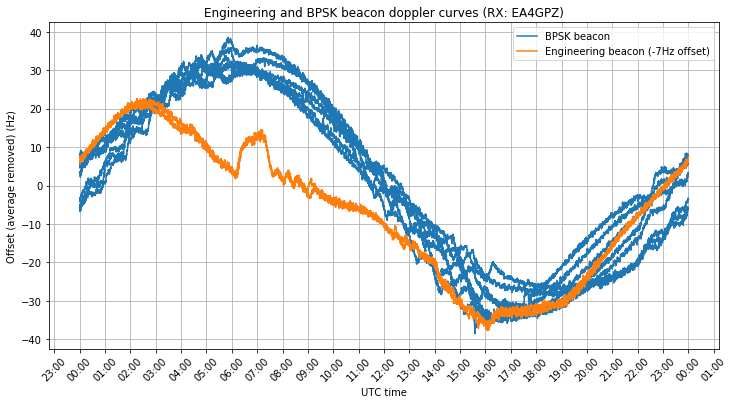
There are a few wiggles in the engineering beacon, especially between 7:30 and 9:00 UTC. There is also the large weird thing between 6:00 and 7:30 UTC. The wiggles don’t coincide at all with those in the BPSK beacon. So one thing is clear, the references used by the engineering beacon and the BPSK beacon are completely independent.
So far we really have no clue about the cause of the wiggles. I have been posting my measurements on a Twitter thread, and several people have commented with ideas. One of the theories is that the wiggles are caused by some thermal effect on the local oscillator that depends on the angle with which the sun illuminates the spacecraft.
Incidentally, it happens that we are currently in a period where the sun declination is low, as the eclipse season has just finished. Indeed, at first I thought that the wiggles were caused by the eclipse, because the start of the first wiggles I measured coincided neatly with the eclipse. It is interesting to note that these wiggles were not present the last time I did precise measurements of the BPSK beacon, near the end of November 2019. At that time the sun declination was much higher, but it is not clear whether this plays a role or is just a coincidence.
Ignoring the slow change in sun declination, the illumination angle repeats every solar day. From the point of view of the satellite, the sun makes a full revolution around the satellite every solar day, in the same manner as we experience it here down on Earth. The fact that the time windows where the wiggles happen seem to occur slightly earlier as the days advance, perhaps indicating a sidereal day period, might contradict this idea that the driving factor is the illumination angle.
Maybe we’ll never know the cause of the wiggles, as it is not easy to measure other spacecraft parameters, and most of the technical information about the satellite is kept under NDA. In any case, these wiggles are an interesting and intriguing phenomenon which is worth looking at.
Hi Daniel,
Several months ago I saw that the signal received by my LimeMini were suffering of some nasty jitter, rapid phase and/or frequency changes.
In order to find out why I started by testing with different LNBs, next was unlocking the psk beacon correction made by SDR-Console and finally receiving my own signal at 2.4 GHz directly without letting being converted inside QO100. My Lime Mini transmission was not completely stable but there were no big jitter like observed through the satellite.
It got clear that some LNBs are very unstable but other seem to be much better.
Propagation changes might have some effects but after reading your work it is clear that satellite local oscillator was not perfect either but we cannot do anything about it. But we can try to transmit as clean as possible,
What can you suggest in order to get the cleanest transmitted signal?
Of course I can try an external reference using a Leo Bodnar GPSDO but I don’t know if there is some kind of problems derived from the PLL inside my radio, the 5V power supply, or maybe even the vibrations of my 4 small blowers moving air on top my Lime Mini.
Would you suggest some clean enough LNBs without the need to lock them to an external reference?
Hi Jose María,
I would say that for the best performance a QO-100 station needs to be completely locked to a GPSDO. This is just my opinion. Other people would say that an LNB with a TCXO is enough, since one can lock to the BPSK beacon in order to correct the LNB drift.
Thanks for your quick answer.
Locking frequency to the bpsk beacon solves the frequency drifts of both LNB and 739 MHz, but many LNBs have a horrible whining or high jitter phase noise. Too many have just a very poor resonator or maybe a tempersture compensated cristal controlled oscillator but with a poorly locked PLL. Frequency drift is not the problem once SDR-Console locks the received frequencies, but phase noise or jitter from LNB and also from the 739 MHz radio receiver bring the worst problems.
I have seen that my LimeMini hardware version v1.2 seems to transmit a pretty clean signal at 2.4GHz but it comes back with a much higher jitter once it goes up and down 76,000 Km and comes back from qo100 converted to 10.4GHz.
I have seen that the transmitted phase noise is not too bad (around 100dBc/Hz at 1KHz) when transmitting a 17dBm carrier at 300MHz, but it is worse at 2140 and 2665 MHz around 88dBc/Hz at 1KHz when maximum carrier level is only close to 0dBm.
Have you ever measured the transmitted jitter of your LimeSDR Mini v1.2 at 2.4GHz?
I may add a relay to switch manually to external or internal 40MHz references, because I do not want to slder the zero ohm resistor to the external path and once doing so needing a GPS receiver always to run my Mini.
I think that the internal tcxo of Mini hardware v1.2 is rated for .5ppm over a wide temperature range. Mine drifts very little once temperature reaches 45°C, but jitter is another story.
Maybe some jitter is coming from my four small blowers or maybe from my simple 7805 voltage regulator.
I read that jitter is related to phase noise.
Do you think that a GPSDO from Leo Bodnar would bring less phase noise to my LimeMini?
I haven’t measured the phase noise of the LimeSDR mini at 2.4 GHz, but I think that the values you state (which more or less match the LMS7002M datasheet) should be pretty close to reality. I don’t think using a GPSDO would improve the phase noise at 1kHz. The main contributor to phase noise is probably the LO synthesizer in the LMS7002M.
I am still not quite sure about what is your problem. You keep talking about jitter, phase noise and frequency stability, but these mean slightly different things to different people. After all, it’s just the same thing over different timescales. So it’s a bit difficult even to imagine what you’re talking about unless you use exact measurements and definitions (like -88dBc/Hz at 1kHz). Some kind of measurement of what you think is wrong with your system (even IQ recording, spectrum, waterfall, or whatever) might help.
Sorry if my thoughts are confusing you. I do appreciate your effort in helping me.
I think that something is wrong with my setup because I see quite a large frequency movement, some kind of jitter going up and down, at a quasi periodic rate of maybe twice per second reaching up to maybe 50Hz off the central frequency, while sending a steady carrier through the satellite. In the first place I thought about some whining by my LNB or maybe the bpsk frequency locking from SDR Console, but other carriers like the CW beacons at band edges while not completely rock steady do not show that much of a jitter when zooming in. Then I thought about my 5V power supply feeding LimeMini and also thought that maybe my 4 small fans moving air on top were transmitting mechanic vibrations to LimeMini, but I do not see such a big frequency driftings while receiving my own signal at 2.4 GHz. So I ended suspecting about something wrong with the transponder and/or the propagation paths for 38 thousand Km, 76,000 in all?
That is how I ended finding your works digging in some kind of problems in the transponder. I do not feel the need for a gpsdo because once reaching a steady temperature my TX frequency does not drift.
I am just looking for my LimeMini being as clean and stable as possible.
BTW… I am Spaniard and my call sign is ea2jx.
Thanks for the SDR Console waterfalls you’ve sent me over email.
To make sure that this isn’t caused by your receiver, have you tried receiving your signal with another receiver, such as the BATC WebSDR? From what I see in the waterfalls, the problem might just be the residual frequency error from the SDR Console Costas loop that locks to the BPSK beacon.
Rest assured that nothing is wrong with the transponder or the propagation path.
I do not see such a swinging when receiving the CW beacons.
I also disconnect the bpsk beacon, suspecting about a poor locking by SDR Console, and I got the same drifting. You can see the resulting screenshot with an evident LNB drifting.
The best clock on earth has an accuracy of 6x(10 elevated to -14) during one day.
If we want to operate through qo100 we better get locked to the dances of this sat than operating with the freedom of the best clock on earth.
I feel that effort concentrates in being locked to the sat, instead of locking for the most expensive clock on earth.
I just read that the best clock on earth, the optical clock, has an accuracy ranging between 2 and 4x(10 elevated to -17) during one second. Curiously they get locked to themselves!
https://en.m.wikipedia.org/wiki/Atomic_clock
If we want to operate through qo100 we better get locked to the dances of this sat than operating with the freedom of the best clock on earth.
I feel that effort concentrates in being locked to the sat, instead of locking for the most expensive clock on earth.
I just had a look at LMS7002M data sheet to find out that has a low noise phase noise at 2.6GHz of -93dBc/Hz at 1KHz.
Since finally transmitted phase noise by LimeMini is a little worse maybe replacing the 40MHz built in tcxo with an external one may be beneficial regarding phase noise.
BTW… I saw that there is a 52MHz clock and a 40 MHz one. I wonder why Lime has two clocks instead of just one like every other transceiver.
The LimeSDR mini doesn’t have a 52 MHz clock. It has a 40 MHz clock that is used for the LMS7002M and a 30 MHz clock that is used for the USB 3.0 controller. Probably the 52 MHz that you’ve seen in the LMS7002M datasheet refers to a specific test set up for the LMS7002M or to the maximum allowable frequency for its reference. As most agile RFICs, the LMS7002M accepts a wide range of frequencies for its reference (10 MHz to 52 MHz).
Understood. After a second look I actually saw that it says that will work with a clock anyway between 10 and 52MHz.
BTW…
I have sent you a couple of emails with screenshots of my transmitted and received carrier swinging 20 to 30 Hz up and down. Have a look if you have a minute.
Thanks a lot!
I already saw those. My reply was in this comment.
I have just sent a reply to your comments above.
For some weird reason my LimeMini seems to swing after being transmitted by the sat.
Other stations have reported that mine swings more than what is considered normal.
The problem is in your transmitter or in your receiver. If other stations report problems in your downlink signal, then the problem is most likely in your transmitter (a good question is whether other stations have measured correctly your downlink signal).
But “seems to swing after being transmitted by the sat” simply can’t happen. Other downlink signals from the transponder are just fine. Moreover, the transponder hardware, including its local oscillator, is of very good quality. Much better than typical Amateur stations.
The problem is in my transmitter. That is probably right, although I cannot find the same swinging when receiving my 2400 transmission.
I wonder what is wrong with my LimeMini.
I was thinking about what you wrote “it can’t happen”.
If my transmitted signal swings a little at 2400… Will it swing 3 times stronger after being converted to 10.4GHz? I am asking because swinging looks much wider after being transmitted by the sat.
I guess that the sat only is mixing the recived spectrum with its L.O. but I have often seen that problems tend to get much worse as frequency is being increased.
The answer to your question is “no”. You’re guessing correctly. Mixing doesn’t multiply the frequency drift.