BY02 telemetry beacon

BY02 (also known as BY70-2) is an Amateur cubesat by the China Aerospace Science and Technology Corporation and Beijing Bayi High School. It was launched on July 3 on a CZ-4B rocket from Taiyuan together with a Gaofen Earth observation satellite. BY02 is intended as a replacement for BY70-1, which was launched on 2016-12-28 and was placed on a short-lived orbit that decayed in a few months because of a launch problem.

Today, Wei Mingchuan BG2BHC announced on Twitter at 09:14 UTC that BY02’s beacon was on and would be left on at least until 12:50 UTC. I believe that this is the first time that the beacon has been on for an extended period of time, since during the early operations the beacon was only active on passes over China.

Since at 11:39 UTC there was a good pass over Spain, I went outside with my handheld Arrow 7 element yagi to do a recording. This post is an in-depth analysis of this recording and includes an explanation of the coding and telemetry format used by BY02.

Playing with LilacSat-1

Even though the cubesat LilacSat-1 was launched more than a year ago, I haven’t played with it much, since I’ve been busy with many other things. I tested it briefly after it was launched, using its Codec2 downlink, but I hadn’t done anything else since then.

LilacSat-1 has an FM/Codec2 transponder (uplink is analog FM in the 2m band and downlink is Codec2 digital voice in the 70cm band) and a camera that can be remotely commanded to take and downlink JPEG images (see the instructions here). Thus, it offers very interesting possibilities.

Since I have some free time this weekend, I had planned on playing again with LilacSat-1 by using the Codec2 transponder. Wei Mingchuan BG2BHC persuaded me to try the camera as well, so I teamed up with Mike Rupprecht DK3WN to try the camera this morning. Mike would command the camera, since he has a fixed station with more power, and we would collaborate to receive the image. This is important because a single bit error or lost chunk in a JPEG file ruins the image from the point where it happens, and LilacSat-1 doesn’t have much protection against these problems. By joining the data received by multiple stations, the chances of receiving the complete image correctly are higher.

Improved signal processing for LilacSat-2 VLBI

Last week I published my results about the LilacSat-2 VLBI experiment. There, I mentioned that there were some things I still wanted to do, such as studying the biases in the calculations or trying to improve the signal processing. Since then, I have continued working on this and I have tried out some ideas I had. These have given good results. For instance, I have been able to reduce the delta-range measurement noise from around 700m to 300m. Here I present the improvements I have made. Reading the previous post before this one is highly recommended. The calculations of this post were performed in this Jupyter notebook.

Amateur VLBI experiment with LilacSat-2

On 23 February, Wei Mingchuan BG2BHC published on Twitter the first Amateur VLBI experiment. This consisted of a GPS-synchronized recording of signals from LilacSat-2 using USRPs in groundstations at Harbin and Chongqing, which are about 2500km apart. Wei has made a Github repository containing the recording (in MATLAB file format) and some signal processing in MATLAB. I have done some signal processing of my own with the recording and published my results in a Jupyter notebook. Here I describe some general aspects about VLBI and its use in Amateur radio, and some specific details of the signal processing I have done.

BER simulation in GNU Radio

David Rowe always insists that you should simulate the bit error rate for any modem you build. I’ve been intending to do some simulations of the decoders in gr-satellites since a while ago, and I’ve finally had some time to do so. I have simulated the performance of the LilacSat-1 decoder, both for uncoded BPSK and for the Viterbi decoder. This is just the beginning of the story, as the code can be adapted to simulate other modems. Here I describe some generalities about BER simulation in GNU Radio, the simulations I have done for LilacSat-1, and the results.

A first look at DSLWP SSDV downlink

The Chang’e 4 is a Chinese lunar mission that will land a rover on the far side of the Moon by the end of 2018. To support this mission, the Chang’e 4 relay satellite will be launched six months before and put into a halo orbit around the Earth-Moon Lagrange L2 point. The relay will provide four 256Kbps links with the rover and lander on X-band and a 2Mbps link with Earth on S-band using a 4.2m dish. Two CE-4 microsatellites will be launched together with the relay satellite. They will be put in a 200km x 9000km lunar elliptical orbit. The main mission of the CE-4 microsatellites is to perform HF interferometry of celestial bodies, using the Moon as a shield from the radiation of the Sun and Earth. The satellites also carry an Amateur radio system called DSLWP, which will provide telecommand, telemetry and image downlink.

A team at Harbin Institute of Technology is currently designing the Amateur radio payload. As it is the case with previous HIT satellites such as BY70-1 and LilacSat-1, the payload will have a camera which can be telecommanded by radio Amateurs, which can use it to take and download pictures. Yesterday, Wei BG2BHC has released some work in progress of the image downlink. Many important parts of the downlink will still change, but releasing the work in progress at this early stage is a very good idea. Probably it is not too late in the development process so that the Amateur community can contribute with ideas and improvements.

The release consists of an IQ recording of the signal containing a full image and a decoder in gr-lilacsat. The IQ recording is at 2ksamp/s, since the signal is FSK at 250baud. Note that the recording is almost 32 minutes long. It takes a while to transmit an image at such a low rate. However, a low baudrate and a good amount of FEC are needed for an effective downlink from the Moon, given the huge path loss of around 197dB in the 70cm band.

The good news about this work in progress is that SSDV is now used to transmit the image. SSDV is a packetised protocol based on JPEG, but which is tolerant to packet loss. In contrast, BY70-1 and LilacSat-1 send JPEG images in 64byte chunks, and a single lost chunk can destroy the image completely. SSDV was originally developed to transmit images from Amateur high altitude ballons, so it is a good idea to use it also for DSLWP.

The bad news is that the way that SSDV has been included into the downlink protocol is not very optimal. In the rest of this post I do an in-depth look at the protocol, point out the main problems and suggest some solutions. Hopefully the protocol can still be modified and improved.

LilacSat-1 downlink usage

In my previous post, I examined a recording of LilacSat-1 transmitting an image. I did some calculations regarding the time it would take to transmit that image and the time that it actually took to transmit, given that the image was interleaved with telemetry packets. I wondered if the downlink KISS stream capacity was being used completely.

You can find more information about the downlink protocol of LilacSat-1 in this post. The important information to know here is that it consists of two interleaved channels: a channel that contains Codec2 frames for the FM/Codec2 repeater and a channel that contains a KISS stream. The KISS stream is sent at 3400bps. At any moment in time, the KISS stream can be either idling, by sending c0 bytes, or transmitting a CSP packet. The CSP packets can be camera packets (which are sent to CSP destination 6) or telemetry packets (and perhaps also other kinds of packets).

I have extracted the KISS stream from the recording and examined its usage to determine if it is being used at its full capacity or if it spends time idling. The image below represents the usage of each byte in the KISS stream, as time progresses. Bytes belonging to image packets are shown in blue, bytes belonging to other packets are shown in red and idle bytes are shown in white. (Remember that you can click the images to view them in full size).

The first 3 or 4 seconds of the graph are garbage, since the signal wasn’t strong enough. Then we see some telemetry packets and the image transmission starts. We observe that most image packets are transmitted leaving an idle gap between them. The size of the gap is similar to the size of the image packet. Every 10 seconds, a bunch of telemetry packets are transmitted, in a somewhat different order each time. Some telemetry packets are sent back to back, and others are interleaved with image packets. Image packets are only sent back to back just after a telemetry transmission.

The next graph shows the usage of the KISS stream averaged over periods of 5 secons. The y-axis means fraction of capacity of the link, so a 1 means that the full 3400bps are used. The capacity spent for image packets is shown in blue and the capacity used for telemetry is shown in red. The green curve is the sum of the blue and red, so it means the fraction of time that the link is not idle. We see that the link is never used completely. The total usage ranges between 60% and 90%, but never reaches 100%.
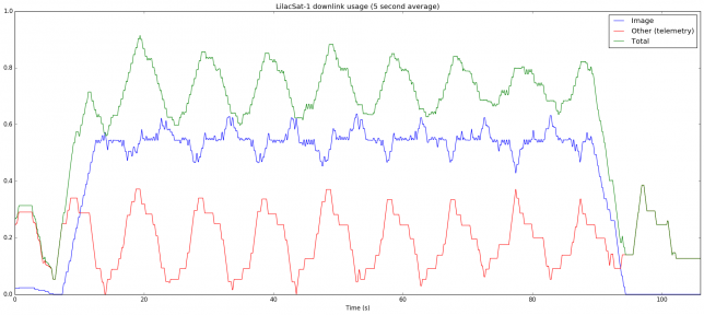
As expected, the capacity used for telemetry spikes up every 10 seconds. The blue curve is more interesting. It is roughly around 55%, but whenever telemetry is sent, it decreases a little. Just after each telemetry burst, the blue curve increases a little. This matches the behaviour we have seen in the previous graph. Every 10 seconds a telemetry burst is sent, using up some capacity that would normally be spent for image. After the telemetry burst, some image packets are sent back to back in a burst, peaking up to 60% capacity, but soon the packets continue being sent with idle gaps between them, and the capacity goes down to 55%.

It is a bit strange that the link is not fully utilised. One would expect that image packets are sent as fast as possible, stopping only to send telemetry. However, we have seen that there are many idle gaps. It seems that the image can’t be read very fast or that there is some other throttling mechanism. This would explain why a burst of image packets is sent after each telemetry burst: the image packets buffer up, because the link is sending telemetry. When the link is no longer busy with telemetry, it sends all the buffered image packets in a row, but soon enough image packets can’t be produced as fast as the link sends them, so idle gaps appear. This seems quite an important performance issue, as it appears that image transmission speed is capped at about 1870bps.

The Python code that generated these graphs can be seen below. The KISS file is also in the same gist.

LilacSat-1 image downlink

Yesterday, Wei BG2BHC posted on Twitter an IQ recording of LilacSat-1 sending an image. LilacSat-1 has an onboard camera and it can send images using the same format as BY70-1. However, one has to keep in mind that in LilacSat-1 the Codec2 frames and the KISS stream with telemetry and image packets are multiplexed as described here, whereas BY70-1 only transmitted the KISS stream with telemetry and image packets. As in the case of BY70-1, the camera is potentially open to telecommand by all Amateurs, although it seems that system is not enabled yet.

The signal in Wei’s recording is very strong and stable, about 20dB SNR in its natural bandwidth of 13kHz. Therefore, it is no surprise that the image can be decoded without errors.

When BY70-1 was in orbit, it was quite difficult for an Amateur station to get a perfect decode of the image, since a single fade in the signal would completely corrupt the JPEG file. LilacSat-1 doesn’t seem particularly stronger than BY70-1, so the same degree of difficulty can be expected. Of course, a well equipped groundstation such as the one in Harbin Institute of Technollogy will have no problems to get a good decode, as shown by this IQ recording. Amateurs with more modest stations should resort to a collaborative effort to try to combine the different packets that form the image, as received by several stations. Currently this procedure can only be partially automated by software, because the CRC algorithm used in LilacSat-1 is not publicly known, so it is not possible to check the packets for bit errors.

LilacSat-1 image 143

The image transmitted by LilacSat-1 can be seen above. Its size is 13861 bytes and it took 217 camera packets and 1 minute and 26 seconds to transmit. This is pretty good, as it means that several images can be taken and transmitted during a pass.

Recall that the downlink of LilacSat-1 transmits at 4800bps, but 1400bps are taken for Codec2, leaving 3400bps for the KISS stream containing image packets (and telemetry packets). Each camera packet contains a 64 byte JPEG chunk, but taking into account headers it is 87 bytes long. We also need to take into account the overhead of the KISS stream. Assuming that no bytes have to be escaped, we just need to include 2 extra bytes for the frame delimiters, so a camera packet takes 89 bytes from the KISS stream and so it takes 197ms to transmit. This means that the image above could have been sent in only 43 seconds. All the extra time is probably due to the fact that the image was sent interleaved with many telemetry packets, although it would be interesting to examine if the KISS stream was in fact completely busy all the time during the image download.

The complete telemetry log decoded from this recording is in this gist. I have also taken the GPS data from the telemetry and plotted it in the map below. The position of the Harbin Institute of Technology, where the recording was made, is also shown.

A 48kHz WAV file extracted from the recording has been included in satellite-recordings. It can be fed directly to the gr-satellites LilacSat-1 decoder.

Testing LilacSat-1 Codec2 downlink and GPS telemetry

Today I’ve finally had some time to test the LilacSat-1 Codec2 downlink on the air. I’ve been transmitting and listening to myself on the downlink during the 17:16 UTC pass over Europe from locator IN80do. The equipment used is a Yaesu FT-2D for the FM uplink, a FUNcube Dongle Pro+ and my decoder from gr-satellites for the downlink, and a handheld Arrow satellite yagi (3 elements on VHF and 7 elements on UHF). Here I describe the results of my test.

A tour of QB50

The QB50 project consists in a constellation of cubesats with the goal of studying the thermosphere. The cubesats are built by different universities around the world and each of them carries one of three different scientific instruments. A total of 36 cubesats have been built for the QB50 project. All of them transmit on the 70cm Amateur satellite band. A total of 28 were launched to the ISS on April 18th on the Cygnus CRS-7 resupply ship. Over the last two weeks, they have been released from the ISS. The complete launch schedule and radio information can be found here (note that the launches on May 23rd were delayed due to an unforeseen EVA). Several other non-QB50 cubesats, some of them transmitting in the Amateur bands, have also been released together with the QB50 satellites. This is probably the time that more Amateur satellite have been released at the same time. The satellites have not separated much yet, giving a great opportunity to record a single pass and analyse the telemetry of all the satellites.

A few days after the release of all the 28 QB50 cubesats, on May 29th at 18:25:29 UTC, I made an SDR recording of the complete pass of all the cubesats. The recording spans the 3MHz of the 70cm Amateur satellite band (435-438MHz) and lasts 23 minutes and 08 seconds. It was made from locator IN80do using a 7 element handheld yagi (the Arrow satellite yagi) held in the vertical polarization and a LimeSDR. The gain of the LimeSDR was set to maximum, but no external LNA was used. Here I look at the recording, list the satellites heard, and decode their telemetry.