Some posts ago, I spoke about the possibility of using the OCXO/Si5351A synth kit from QRP Labs as a low cost way of providing an external stable 27MHz reference to a satellite LNBF. I’ve received and built my kit some days ago, so here I will be looking at some aspects in the construction and performance of this kit.
Month: February 2016
Calibrating the S-meter in Linrad
In a previous post, I talked about the GALI-39 amplifier kit from Minikits. Here I will describe the procedure to calibrate the S-meter in Linrad (or another SDR) using this amplifier or any other amplifier with a known NF and an uncalibrated signal source. Leif Åsbrink has a youtube video where he speaks about the calibration of the S-meter in Linrad. However, he doesn’t use an amplifier, so I will be following a slightly different procedure.
Building the GALI-39 amplifier kit from Minikits
The GALI-39 is a DC-7GHz MMIC amplifier from Minicircuits. This device has a gain around 20dB and a NF of about 2.4dB. The nice thing about MMICs is that their input and output impedances are matched to 50Ω, so it’s quite easy to work with them. Minicircuits makes many MMIC amplifiers suiting different needs, but unfortunately their products are not so easy to get in small quantities.
Minikits.com.au is an Australian store that sells Minicircuits parts in small quantities as well as many interesting RF kits. I needed some RF amplifier having a known NF to do some signal level calibrations, so I ended up ordering the GALI-39 amplifier kit from Minikits. This kit includes just the GALI-39, a PCB and the handful of SMD components you need to bias the amplifier. At 22AUD, the price of the kit is about right and buying the kit instead of just the GALI-39 saves me to do the shopping for the assorted SMD components and using the PCB instead of botching some circuit is always nice, because the PCB uses microstrip transmission line (but the substrate is regular FR-4). Here I have a look at what is included in the kit (I’ve been unable to find a complete list on Minikit’s web).
An idea for a low cost stable 10GHz receiver
The satellite Es’Hail-2 is expected to be launched by the end of 2016. This will be the first geostationary satellite carrying an amateur radio transponder. As the launch date comes nearer, it becomes interesting to find a low cost solution to receive its 10GHz downlink.
Several amateurs have been experimenting with low cost LNBFs designed to receive satellite TV. These operate in the Ku band and usually cover the frequencies 10.7GHz-12.75GHz. However, many of these LNBFs have also good performance in the X band, and particularly in the amateur 10GHz band (10GHz-10.5GHz). In fact, the ASTRA-type LNBFs have a local oscillator which can be setted to either 9.75GHz or 10.6GHz. The 9.75GHz local oscillator mixes 10.386GHz (the narrowband terrestrial subband) to 618MHz, which is a frequency covered by most SDRs and conventional scanners. The satellite subband, which is 10.45GHz-10.5GHz gets mixed down to 700MHz-750MHz, a frequency which is also easy to deal with.
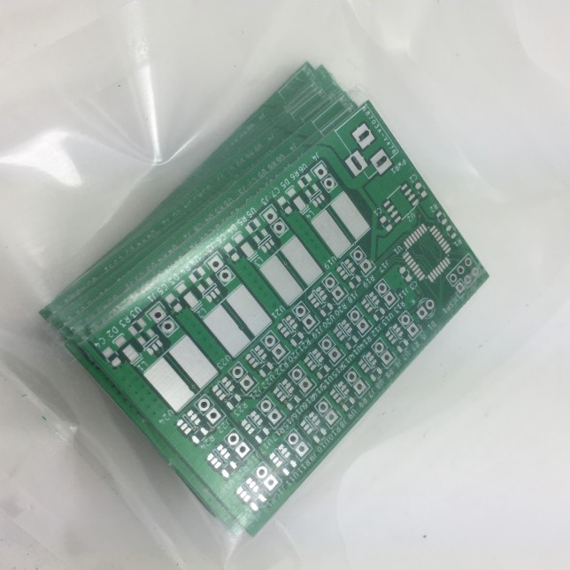
Arduino LED driver: PCBs shipped
This is a quick introduction to my Arduino LED driver project, since the PCBs for the prototype have being shipped from ShenZhen2U a couple of days ago. This project is fairly simple. The idea is to have an Arduino-compatible ATmega328P drive many LED strings, composed of one of the following two types of LEDs: regular or high-efficiency LEDs taking about 30mA, and high-power LEDs modules taking between 700mA and 1A. The applications I have in mind for this project are several lightning projects where a bunch of LEDs have to be controlled, perhaps in a complex way, but without needing much input (or none at all) from the outside world. Christmas and party lightning are good examples.
A total of 4 AL8808 switching mode LED drivers can be installed on the PCB to drive strings of high-power LEDs requiring up to 1A of current. To drive strings of regular LEDs, the BCR420UW6 linear mode LED driver is used. A total of 18 of these can be installed on the PCB. This is as much as you can control with the ATmega328P, as all of the output pins get used.
No USB is included in this project, since the idea is to program it via ISP. In case some interaction with the outside world is needed, the ISP header could be used to interface with SPI hardware. Everything runs off 12VDC which has to be provided by an external switching mode power supply.

This is going to be open source hardware, so when I have actually built and tested the project I will post the schematics and PCB layouts to Github. Stay tuned for more information.