The Chang’e 4 is a Chinese lunar mission that will land a rover on the far side of the Moon by the end of 2018. To support this mission, the Chang’e 4 relay satellite will be launched six months before and put into a halo orbit around the Earth-Moon Lagrange L2 point. The relay will provide four 256Kbps links with the rover and lander on X-band and a 2Mbps link with Earth on S-band using a 4.2m dish. Two CE-4 microsatellites will be launched together with the relay satellite. They will be put in a 200km x 9000km lunar elliptical orbit. The main mission of the CE-4 microsatellites is to perform HF interferometry of celestial bodies, using the Moon as a shield from the radiation of the Sun and Earth. The satellites also carry an Amateur radio system called DSLWP, which will provide telecommand, telemetry and image downlink.
A team at Harbin Institute of Technology is currently designing the Amateur radio payload. As it is the case with previous HIT satellites such as BY70-1 and LilacSat-1, the payload will have a camera which can be telecommanded by radio Amateurs, which can use it to take and download pictures. Yesterday, Wei BG2BHC has released some work in progress of the image downlink. Many important parts of the downlink will still change, but releasing the work in progress at this early stage is a very good idea. Probably it is not too late in the development process so that the Amateur community can contribute with ideas and improvements.
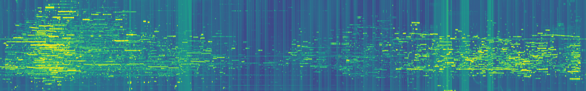
The release consists of an IQ recording of the signal containing a full image and a decoder in gr-lilacsat. The IQ recording is at 2ksamp/s, since the signal is FSK at 250baud. Note that the recording is almost 32 minutes long. It takes a while to transmit an image at such a low rate. However, a low baudrate and a good amount of FEC are needed for an effective downlink from the Moon, given the huge path loss of around 197dB in the 70cm band.
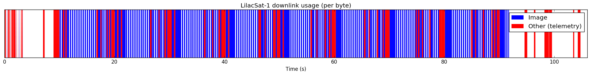
The good news about this work in progress is that SSDV is now used to transmit the image. SSDV is a packetised protocol based on JPEG, but which is tolerant to packet loss. In contrast, BY70-1 and LilacSat-1 send JPEG images in 64byte chunks, and a single lost chunk can destroy the image completely. SSDV was originally developed to transmit images from Amateur high altitude ballons, so it is a good idea to use it also for DSLWP.
The bad news is that the way that SSDV has been included into the downlink protocol is not very optimal. In the rest of this post I do an in-depth look at the protocol, point out the main problems and suggest some solutions. Hopefully the protocol can still be modified and improved.