Simulating JT modes: how low can they get?

In this post I’ll show how one can use the signal generation tools in WSJT-X to do decoding simulations. This is nothing new, since the performance of the modes that WSJT-X offers has being thoroughly studied both with simulations and real off-air signals. However, these tools seem not very widely known amongst WSJT-X operators. Here I’ll give some examples of simulations for several JT modes. These can give the operators a hands-on experience of what the different modes can and cannot achieve.

Please note that when doing any sort of experiments, you should be careful before jumping to conclusions hastily. You should make sure that the tools you’re using are working as they should and also as you intend to (did you enter correctly all the parameters and settings?). Also, you should check that your results are reproducible and agree with the theory and other experiments.

Another warning: some of the software that I’ll be showing here, in particular the Franke-Taylor soft decoder for JT65 and the QRA64 mode, is still under development. The results that I show here may not reflect the optimal performance that the WSJT-X team aims to achieve in the final release version.

After all these warnings, let’s jump to study the modes. We’ll be considering the following modes: WSPR, JT9A, JT65A, JT65B and QRA64B. To give our tests some purpose, we want to find the decoding threshold for these different modes. This is the signal to noise ratio (SNR) below which the probability of a successful decode is too small to be useful (say, lower than 20%). For each mode, we will generate 100 test files containing a single signal with a fixed SNR. We will then see how many files can be successfully decoded for each SNR.

Decoding GOMX-1 telemetry

GOMX-1 is a 2U cubesat from GomSpace that was launched in November 2013 into a sun-synchronous orbit. As far as I know, it was the first satellite with an ADS-B receiver payload. It transmits telemetry on the 70cm Amateur band, including some data from the ADS-B receiver, as GOMX-3 does. Some Amateurs, including me, had tried to decode its telemetry on several occasions, without success. GOMX-3 will decay in about 4 weeks, as it was launched from the ISS on October 2015. Therefore, it now becomes more interesting to decode GOMX-1, which is in a longer term orbit. After one more serious try, I’ve been able to decode the telemetry. This is the first time that an Amateur decodes telemetry from GOMX-1 completely. The decoder code can be found in gr-satellites and gr-ax100, including an example wav file in gr-ax100/examples/gomx-1.wav.

A brief try at decoding HORYU-4 1k2 AFSK telemetry

In the previous post I’ve talked about HORYU-4 CW telemetry. Here I report my findings when trying to decode 1200baud AFSK telemetry. Since the satellite transmits digital telemetry only over Japan, the recordings I’ve analysed have being kindly provided by Tetsurou JA0CAW. There is a telemetry format document from Kyutech, but as it is the case with the CW document, it is rather incomplete and lacks several important details.

How hard is it to decode 3CAT-2?

In a previous post, I looked at the telemetry packets transmitted by the satellite 3CAT-2. This satellite transmits 9600bps AX.25 BPSK packets in the Amateur 2m band. As far as I know, it is the only satellite that transmits fast BPSK without any form of forward error correction. LilacSat-2 uses a concatenated code with a (7, 1/2) convolutional inner code and a (255, 223) Reed-Solomon outer code. The remaining BPSK satellites transmit at 1200bps, either using AX.25 without FEC (the QB50p satellites, for instance), or with strong FEC (Funcube, for example). Therefore, I remark that 3CAT-2’s packets will be a bit difficult to decode without errors. But how difficult? Here I look at how to use the theory to calculate this, without resorting to simulations.

RS92-SGP: trying to change the frequency with an external reference

In a previous post, I talked about the possibility of changing the transmit frequency of a Vaisala RS92-SGP radiosonde by modifying the settings on its EEPROM. The lowest frequency you can achieve using this method is 400MHz and the highest probably depends on the particular unit, but it is somewhat between 410MHz and 423MHz. There are also reports of very low output power on the highest frequencies (I’ll explain why below). Clearly, this can’t be used to make the radiosonde transmit in 430MHz, inside the 70cm Amateur band. In fact, from what I’ve read online, the impression is that it’s not possible to modify the radiosonde to make it transmit in 430MHz. However, I wanted to try to feed an external reference to see what happened. Short story: it doesn’t work either. However, I discovered some interesting information about the RF section of the RS92-SGP along the way.

Receiving the Vaisala RS92-SGP radiosonde launched from Madrid-Barajas

Each day, at 01:00UTC and 11:00UTC a Vaisala RS92-SGP radiosonde is launched from Madrid-Barajas airport. This is a small electronics package tied to a helium balloon that ascends up to between 24 and 28km high before bursting and descending on parachute. It is designed to measure atmospheric parameters on its way up. It includes temperature, pressure and humidity sensors, as well as a GPS receiver. The launch on Wednesdays at 11:00UTC also includes a plug-in ozone sensor (which is a much larger and more expensive package). The data is transmitted at 403MHz using Manchester-encoded 4800bps GMSK and protected using Reed-Solomon. You can find more information about the RS92-SGP model in its technical datasheet and about the launches at Madrid-Barajas and other launches in Spain in the Spanish AIP Section 5.3 (other activities of a dangerous nature). Also, there is somebody who feeds the radiosonde data into the APRS network using SM2APRS, so you can track the launches by following OKER-11 on aprs.fi.

Usually, the Sondemonitor software is used to receive and plot the parameters measured by the radiosonde and track the GPS data. Of course, this program is very nice and complete, but it is shareware, costs 25€ and runs only in Windows. I wanted to try if it is possible to track the GPS data in Linux using free software.

Update on phase noise of 27MHz references

This is a follow up to a previous post where I investigated the phase noise of 27MHz references to be used for a 10GHz receiver. Dieter DF9NP has being kind enough to send me a 10MHz 0.25ppm TCXO to do some more tests.

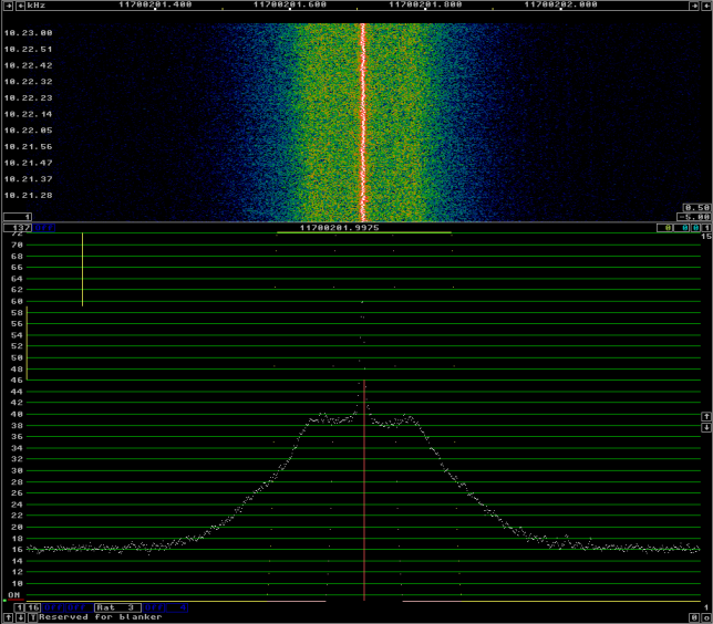
I’ve connected the 10MHz TCXO to the DF9NP 27MHz PLL and used it to receive the beacon of BADR-5, as I did in the previous post. The phase noise of the 10MHz TCXO + 27MHz PLL can be seen in the following figure.

10MHz 0.25ppm TCXO and 27MHz PLL

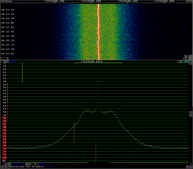
For comparison, see below the phase noise with the DF9NP 10MHz GPSDO and 27MHz PLL. There is not much difference between both. This seems to indicate that the culprit of the phase noise is the 27MHz PLL, as the 10MHz TCXO should be quite clean.

10MHz GPSDO and 27MHz PLL

Phase noise of a Baofeng UV-5R 10GHz signal

Several of the Baofeng chinese handheld radios generate a weak 10GHz signal while in receive mode. Thus, they are a popular cheap and quick 10GHz signal source for tests. To generate a 10GHz signal, you have to tune the Baofeng to the 70cm band (for instance, 432MHz). The radio will generate a weak 24th harmonic while in receive mode. If you want a steady carrier, you have to set the squelch to zero. Otherwise you will just get beeps as the radio wakes up periodically to check for a signal. Lately, I’ve being investigating phase noise and reciprocal mixing of 10GHz receiver systems. A natural question is how good is the phase noise of a Baofeng used as a 10GHz signal source and whether it can be used to check if the phase noise performance of a receiver is acceptable. It turns out that it is not so noisy as one may first think.

Ship reflection on ED5YAE 10GHz beacon

In my previous post, I mentioned the possibility of receiving 10GHz beacons reflecting off ships in the Mediterranean sea through the Paella Team WebSDR, in Alicante. Luis EA5DOM tells me that these reflections happen often. However, I didn’t get any in the time I was doing the recordings for the previous post.

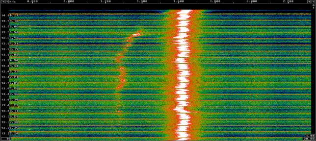
After making much longer recordings, I have seen a couple of reflections. I would say that a dozen or so happen every day. However, they last for quite long. Here you can see a reflection lasting for almost 20 minutes. The Doppler shift ranges between -300Hz and -200Hz. At its strongest moment, the reflection is only 10dB weaker than the beacon.

ED5YAE: direct signal and reflection