In a previous post, I recorded and decoded LilacSat-2 telemetry. This satellite transmits telemetry on 437.200MHz and 437.225MHz using two different radios and antennas, as can be seen in the radio info page. The transmission on 437.200MHz is usually 9k6 BPSK telemetry, but this is the same frequency, radio and antenna that is used for the amateur FM transponder when it is active. Looking at the waterfall as I recorded the IQ, I had the impression that the signal on 437.200MHz was much weaker than the signal on 437.225MHz. Using my LilacSat-2 receiver and the IQ recording I did, I have plotted the signal strength on both frequencies to compare.
Author: destevez
LilacSat-2 GNUradio receiver
I have made my own LilacSat-2 telemetry GNUradio receiver using the flowgraphs included in gr-lilacsat. The new features of this receiver are the following:
- All the decoders and the frontend are run on the same flowgraph. I find this more practical than having to run all the flowgraphs separately. Also, some blocks can be reused in this way.
- It uses gr-gpredict-doppler to compensate for Doppler. As I mentioned in a previous post, I prefer this to the Doppler correcting system included in
gr-lilacsat. - It plots and outputs to a file the signal strength on 437.200MHz and 437.225MHz. This can be used for later analysis.
- It supports recording file input, or live SDR using an ALSA source (for the FUNCube Dongle Pro+, for instance). Another SDR supported by GNUradio can be easily used.
- It supports recording both the raw IQ data and the Doppler corrected IQ data. The raw IQ file can be then played back by simultaneously running Gpredict with the correct settings for the recorded pass. The Doppler corrected IQ file can be played back without running Gpredict.
This receiver can be downloaded from GitHub. The flowgraph is a bit crammed, but that’s what you get for having all the decoders in the same flowgraph. Several of the input/output blocks are disabled, so that you can choose which ones to use.
LilacSat-2 telemetry PDU decoder
Recently, I showed my experiences receiving and decoding LilacSat-2 telemetry. I managed to get 15 packets of 4k8 GFSK telemetry and 15 packets of 9k6 BPSK telemetry during a single pass. However, I couldn’t decode these packets because I didn’t know the telemetry format. It turns out that Mike DK3WN has released a decoder software. Here I show Mike’s software decoding the packets I received.
Decoding LilacSat-2 telemetry
After having my first QSO through the Harbin Institute of Technology amateur radio satellite LilacSat-2, I decided to give a serious try to the telemetry decoding software. This is available as a GNURadio module. A Linux distribution with all the proper software installed and configured is provided, for an easy use. However, I have used GNURadio in the past, so I wanted to try to setup the GNURadio module directly on my machine.
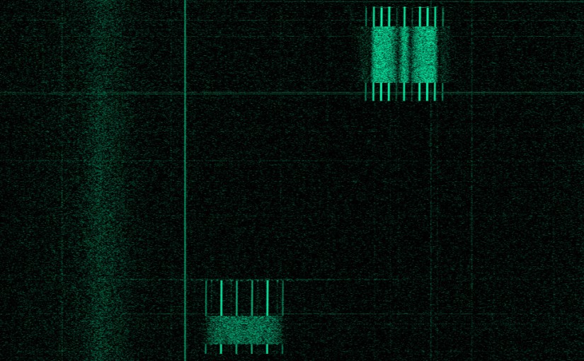
The web page for LilacSat-2 gives also a description of the different telemetry formats. The satellite has an SDR radio transmitting on 437.200MHz. This radio is used for the FM amateur radio transponder and also to transmit several different telemetry formats. The satellite also transmits telemetry on 437.225MHz, presumably using a different (non-SDR) radio and a different antenna, so that the satellite can keep transmitting telemetry even if the SDR system fails. Typically, when the FM transponder is disabled, the satellite will transmit 9k6 BPSK telemetry on 437.200MHz and 4k8 GFSK telemetry on 437.225MHz. These can be seen in the picture above, which was made using my RF recording and baudline. The packet on the upper right is 4k8 GFSK and the packet on the lower left is 9k6 BPSK. Notice the slight slant due to Doppler.
Another look at recursive quadrature oscillators
In a recent post, we looked at which \(2\times 2\) Toeplitz real matrices \(T\) gave useful quadrature oscillators by the recurrence \(x_{n+1}=T x_n\). There, we computed their eigenvalues and solved the recurrence in terms of them. Of course, there are many other ways to approach this problem. Here we look at another approach that gives a good geometric picture of what happens, can be applied to general \(2\times 2\) matrices, and may be used as a starting point for the \(n\times n\) case.
A look at a new digital quadrature oscillator
Two sinusoidal signals are said to be in quadrature if they have a constant phase difference of 90º. Quadrature signals are widely used in signal processing. A digital quadrature oscillator is just an algorithm that computes the sequence \(x_n = (\cos(\omega n), \sin(\omega n))\), \(n\geq 0\), or a similar sequence of sinusoids in quadrature. Here \(\omega\) is the oscillator frequency in radians per sample. Direct computation of this sequence is very time consuming, because the trigonometric functions have to be evaluated for each sample. Therefore, it is a good idea to use a linear recurrence scheme to compute \(x_n\). Using basic trigonometric identities, we see that\[x_{n+1} = A x_n,\quad x_0=\begin{pmatrix}1\\0\end{pmatrix},\]with\[A = \begin{pmatrix}\alpha_1 & -\alpha_2\\\alpha_2 & \alpha_1\end{pmatrix},\quad \alpha_1 = \cos(\omega),\ \alpha_2=\sin(\omega).\]
However, to actually perform these computations in a digital processor, one has to quantize \(\alpha_1,\alpha_2\), meaning that one has to replace \(\alpha_1,\alpha_2\) by approximations. It is easy to see that if one replaces \(\alpha_1,\alpha_2\) by some perturbation, then the eigenvalues of \(A\) are no longer in the unit circle, so the oscillation can grow or decay exponentially and one would need to apply an AGC scheme to keep this method stable.
Here we will look at a new quadrature oscillator by Martin Vicanek that has appeared recently and solves this problem.
Listening to the FreeDV net by WebSDR
Since I’m away from my usual QTH, I decided to join yesterday’s FreeDV net by listening through the University of Twente WebSDR and giving signal reports on the QSO Finder to the stations transmitting.

