In the previous post, I detailed my experiments transmitting FT8 through the FO-29 linear transponder. I recorded a complete pass of the FO-29 satellite while I transmitted an FT8 signal trough the transponder on even periods. As I promised in that post, I have now made a waterfall with the recording to show the activity through the linear transponder, and the strength of my FT8 signal in comparison with the SSB and CW signals of other users.
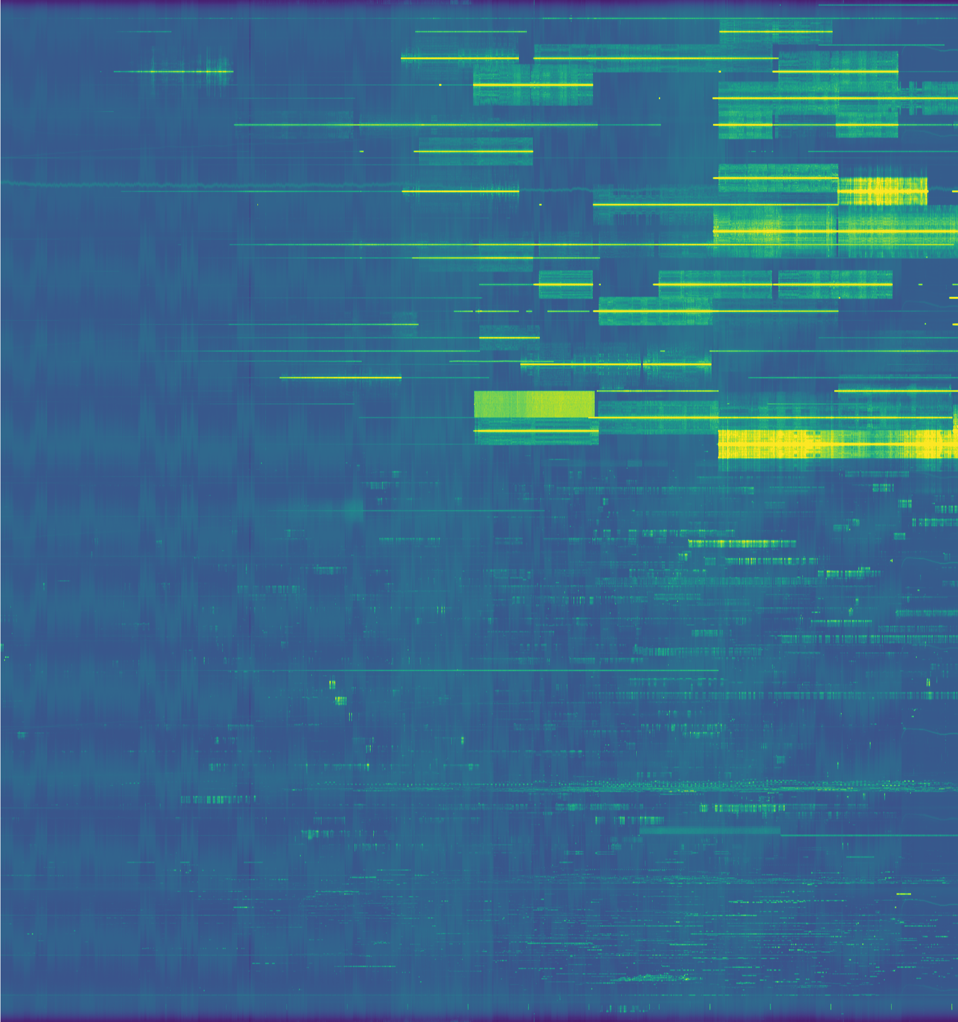
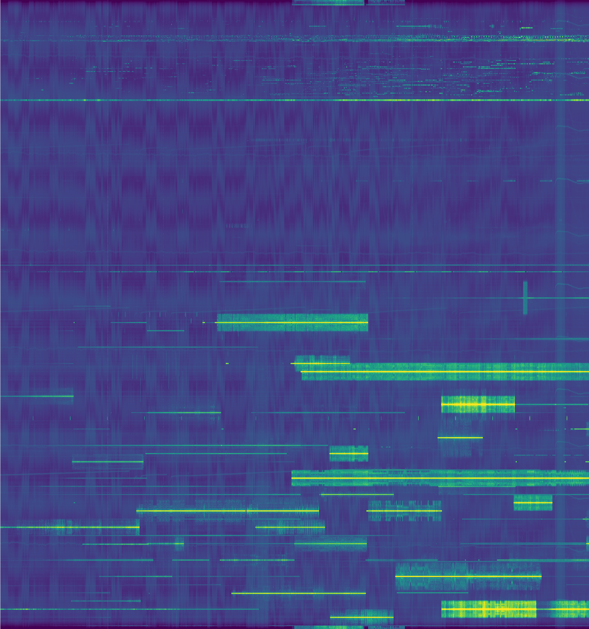
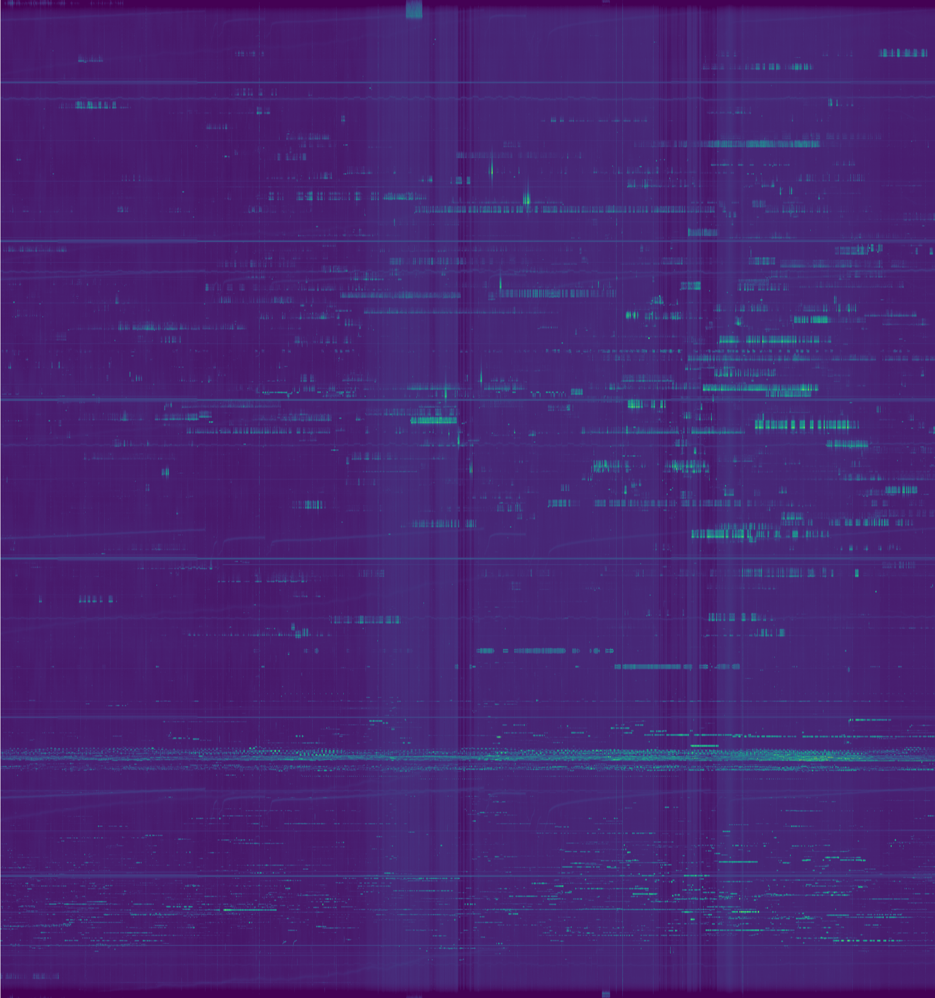
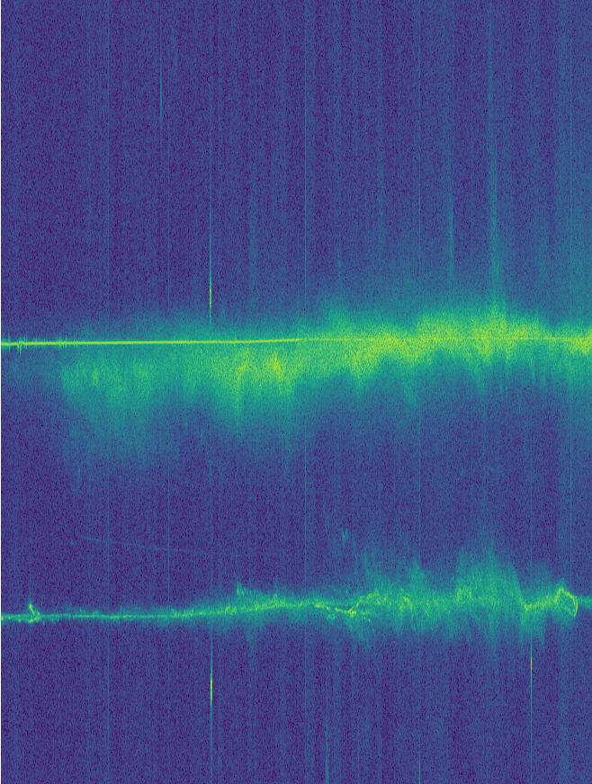
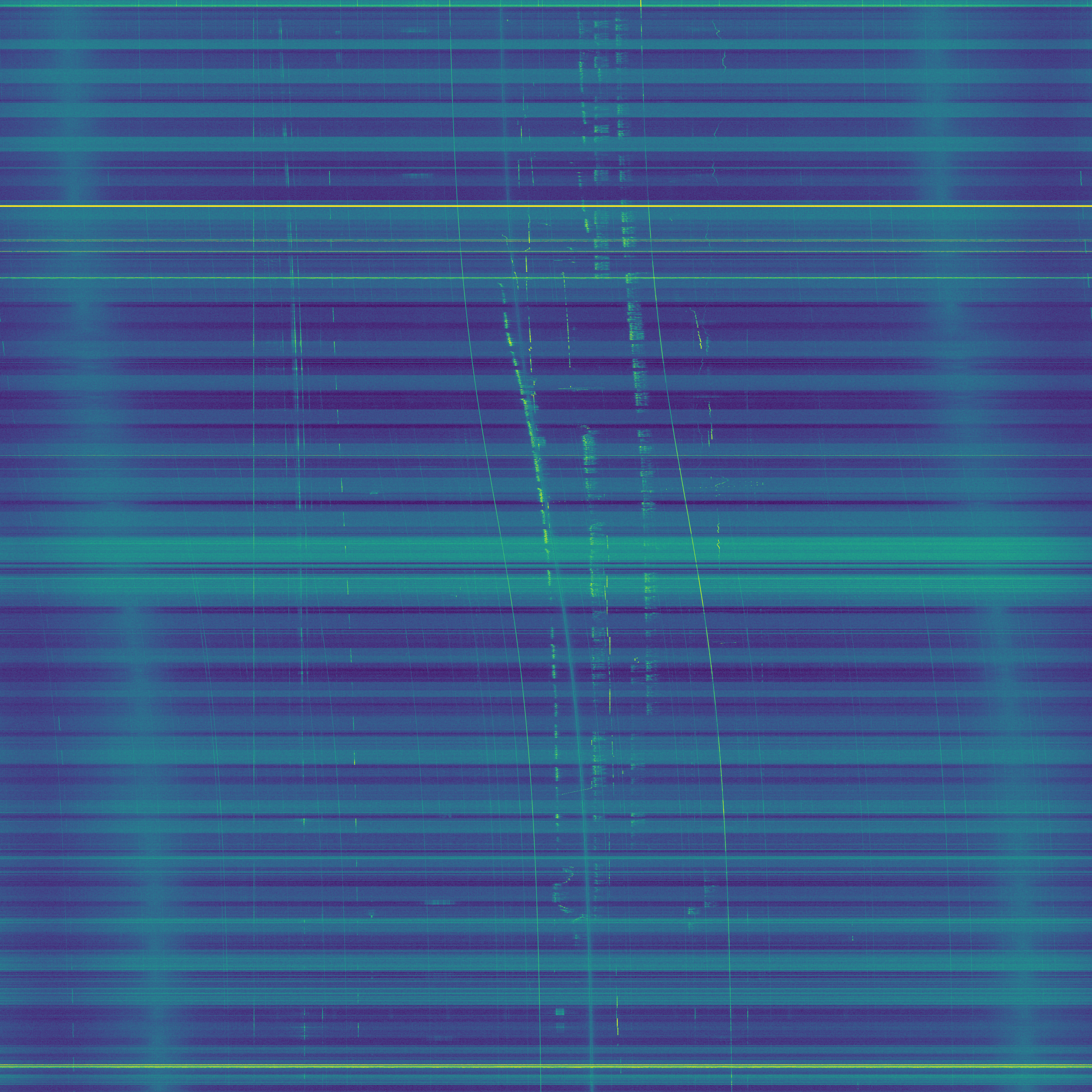
The watefall can be seen below. You can click on the image to view it in full size. A higher resolution version is available here (24MB). The horizontal axis represents frequency and the vertical axis represents time, with the beginning of the pass at the top of the image. The waterfall has been corrected for the downlink Doppler and the DC spike of the FUNcube Dongle Pro+ has been removed.
From left to right, the following signals can be seen: The CW beacon can be seen as a faint vertical signal. Next, there is some interference coming through the transponder in the form of terrestrial FM signals. Then we can see my FT8 signal, being transmitted only on even periods. Finally, around the centre of the image, we have a few SSB and CW signals through the transponder. Note that most of these signals increase in frequency as the pass progresses. This is because many people keep a fixed uplink and only tune the downlink by hand to correct for Doppler. Unfortunately, full computer Doppler correction is not very popular. I also used a fixed uplink frequency for my FT8 signal, but only to simplify the experiment. The best procedure is to correct for the uplink Doppler to keep a constant frequency at the satellite.
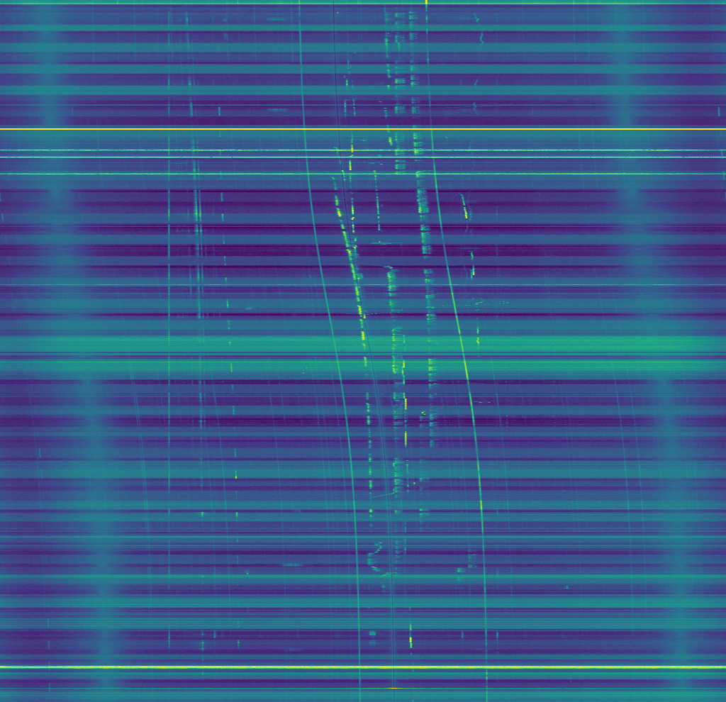
We can see that the SSB and CW signals are much stronger than my FT8 signal. Indeed, some of the CW signals are particularly strong at times, perhaps putting too much pressure on the linear transponder.
The waterfalls in this post have been created using this Jupyter notebook.