Continuing with my frequency measurements of Es’hail 2, I have now been measuring the frequency of the beacons of the QO-100 narrowband transponder for several days. The main goal of these frequency measurements is to use Doppler to study the orbit of Es’hail 2. Previously, I had been doing frequency measurements on the engineering beacons at 10706MHz and 11205MHz. However, these beacons are currently being transmitted on a MENA beam, so I’m quite lucky to be in Spain, as they can’t be received in many other parts of Europe.
During the in-orbit tests of Es’hail 2, the engineering beacons were transmitted on a global beam, and I performed some differential Doppler studies with Jean Marc Momple 3B8DU, in Mauritius. The engineering beacons are no longer any good for these kind of studies, since their area of coverage is small. Thus, I have started to measure the beacons in the narrowband transponder, which covers all the satellite footprint.
There are two beacons on the narrowband transponder, a 400baud BPSK beacon and a CW beacon. The natural choice for frequency measurement is the BPSK beacon, since it transmits continuously and its carrier frequency can be measured with a Costas loop. In comparison, the keying of the CW beacon gives problems with a frequency measurement using a PLL. However, there are two tones of several seconds at the end of each transmission where the PLL can lock on well.
My receive system is a 1.2m offset dish, a Ku-band LNB and a LimeSDR. Everything is locked to a GPSDO by DF9NP. The beacons are transmitted from the new teleport of Es’hailSat in Qatar. The transmit frequency is locked to GPS. However, because of the way that the beacons are generated digitally in a Red Pitaya, the carrier frequency of each beacon has a resolution of 5.85Hz, so its transmit frequency is not “exact”. The reason for this is that the carrier is generated by a 16 bit NCO clocked at 384ksps.
Also, the downlink frequency of the beacons is not the same as published (10489.55MHz for the CW beacon and 10489.8MHz for the BSPK beacon), due to the offset of the local oscillator of the transponder. Currently, the beacons are approximately 144Hz higher than the specification.
At first, I started measuring the frequency of the BPSK beacon, since this was my main interest. However, Wouter Jan Ubbels PE4WJ started measuring the frequency of the CW beacon in order to derive a frequency reference from the 250kHz difference of both beacons. He observed that the difference was approximately 3.9Hz smaller than the published value of 250kHz, and wanted other people to confirm his finding, so I also started to measure the CW beacon. His findings were confirmed by Remco den Besten PA3FYM and me, and later explained by Mario Lorenz DL5MLO as the limitation in the resolution of the NCOs generating the beacon carriers that I have mentioned above.
To perform the measurements, I’m using GNU Radio. My flowgraph can be found here. It has become rather busy, since I’m doing frequency and power measurements of both beacons, and also sending the IQ stream to Linrad using gr-linrad. However, I guess it could be useful to other people. The measurements are then processed in this Jupyter notebook.
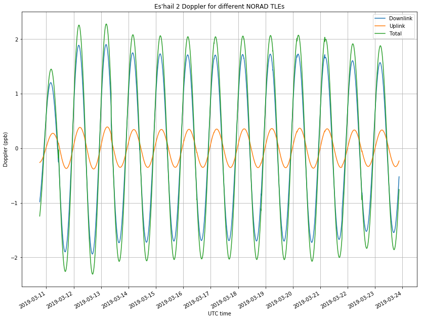
When comparing the Doppler measured on the beacons to the NORAD TLEs, one has to take into account both the downlink Doppler between the satellite and the receiving groundstation, as well as the uplink Doppler between the satellite and the teleport in Qatar. Since the transponder is non-inverting, the total Doppler is the sum of the uplink Doppler and the downlink Doppler.
The figure below shows the Dopplers computed for my groundstation. The units are parts per billion referred to the 10489.8MHz carrier frequency of the BPSK beacon. Note that the uplink Doppler is only 0.23 times the downlink Doppler, due to the frequency ratio between the S-band uplink and the X-band downlink.
As usual, I’m averaging my measurements in windows of 10 minutes to get a reasonable measurement noise. The figure below shows the comparison of my measurements of the BPSK beacon with the NORAD TLEs. We see that the Doppler fits the predictions more or less well.
The figure below shows the difference between the BPSK beacon frequency minus 250kHz, and the CW beacon frequency, in units parts per billion in 250kHz. The large offset of approximately -15550ppb is due to the offset of -3.9Hz mentioned above. An averaging window of 15 minutes has been used.
Even though the measurements have a noise on the order of 10ppb, the Doppler is clearly visible. This may come as a surprise to some people. Indeed, Remco argued that the Doppler would be minimal, due to the ratio of the carrier frequencies of the CW and BPSK beacons being very close to one. This is true, but if you do all the calculations you will see that the 250kHz difference is affected by approximately 1.25mHz peak-to-peak of Doppler, or 5ppb, as my measurements show.
My favourite way of thinking about this is that every temporal or frequency aspect of a modulation (carrier frequency, carrier spacing, baudrate, etc.) is affected by Doppler in the same amount if one measures it is parts per one (or parts per billion) referred to the frequency being studied. In this case, the Doppler that affects the beacons is 5ppb peak-to-peak, regardless of whether we study the carrier frequency of each beacon or the 250kHz carrier spacing, or even the 400 baud of the BPSK beacon.
Of course, if we measure an aspect of lower frequency, we will need a much more precise measurement to get the same measurement noise when expressed in ppb. This is the reason why the 250kHz difference is much more noisy than the carrier frequencies of the beacons (nearly 42000 times more noisy, indeed). Thus, even though the carrier frequency of the BPSK beacon is affected by the drift in the transponder local-oscillator, while the 250kHz difference is not, the carrier frequency of the BPSK beacon is much more useful to study the Doppler, as it is much less noisy.
Returning to Wouter’s plan of using the 250kHz difference to derive a frequency reference, his idea is to correct in software the frequency drift of a free running groundstation. The groundstation he has in mind has an LNB that runs off its own crystal oscillator and an SDR which uses its own TCXO and is used both to receive the narrowband transponder at the IF of the LNB and to transmit directly at 2.4GHz on the uplink.
In this case, the drift of the LNB (plus the drift of the SDR, actually) can be compensated by locking a PLL to the BPSK beacon, so the transponder doesn’t drift. However, for transmitting, the drift of the SDR has to be computed and corrected. The idea is to measure the 250kHz difference, which will be affected by the drift in the sample rate of the SDR. Using this measurement, the drift of the SDR TCXO can be computed and corrected when transmitting.
Now, my measurements show that with a few minutes of averaging, the 250kHz difference can be accurately measured to 20ppb (and we can ignore Doppler here, since it is much smaller than 20ppb). When the transmit frequency is corrected using this measurement, we will have a frequency error of 50Hz, which is probably good enough form many applications.
Onb the cw beacon is it the lowest tone or highest tone that is the correct carrier frequency to read and use to callibrate our receiver QRG? (mark or space tone?)
Hi Jan,
With the current FSK CW beacons, the space (that is, the lower tone for the low beacon, the higher tone for the high beacon) is closest to the published frequency (10489.5 and 10490 MHz). However, depending on how much accuracy you want, using these tones may not be enough, due to Doppler, sample rate errors with the transmitter at Bochum, etc.