I have already spoken about the Moonbounce signal from DSLWP-B that was received in Dwingeloo on 2018-10-07. I have matched it against the Doppler predictions and cross-correlated it against the direct signal. Since the reflected signal presented a high Doppler spread, decoding the GMSK data from the reflected signal would be very difficult or impossible.
On the other hand, JT4G is a digital mode designed for Earth-Moon-Earth microwave communications, so it is tolerant to high Doppler spreads. However, the reflections of the B0 transmitter at 435.4MHz, which contained the JT4G transmissions, were very weak, so I had not attempted to decode the JT4G Moonbounce signal.
On 2018-10-19, the Moonbounce signal from DSLWP-B was again visible in Dwingeloo’s recordings. I have used the 2018-10-19T17:53:35 435.4MHz recording and managed to decode the Moonbounce signal of one out of the five JT4G transmissions that appear in the recording.
To extract the data from the recording to WAV files that can be read by WSJT-X, I have used the following Jupyter notebook. Then I have used WSJT-X version 2.0.0-rc3 to try to decode the Moonbounce signal. Since the JT4 decoder only decodes a single signal at the selected frequency, it is enough to select the frequency of the Moonbounce signal in WSJT-X. The direct signal will not be decoded, even though it is also present in the WAV file.
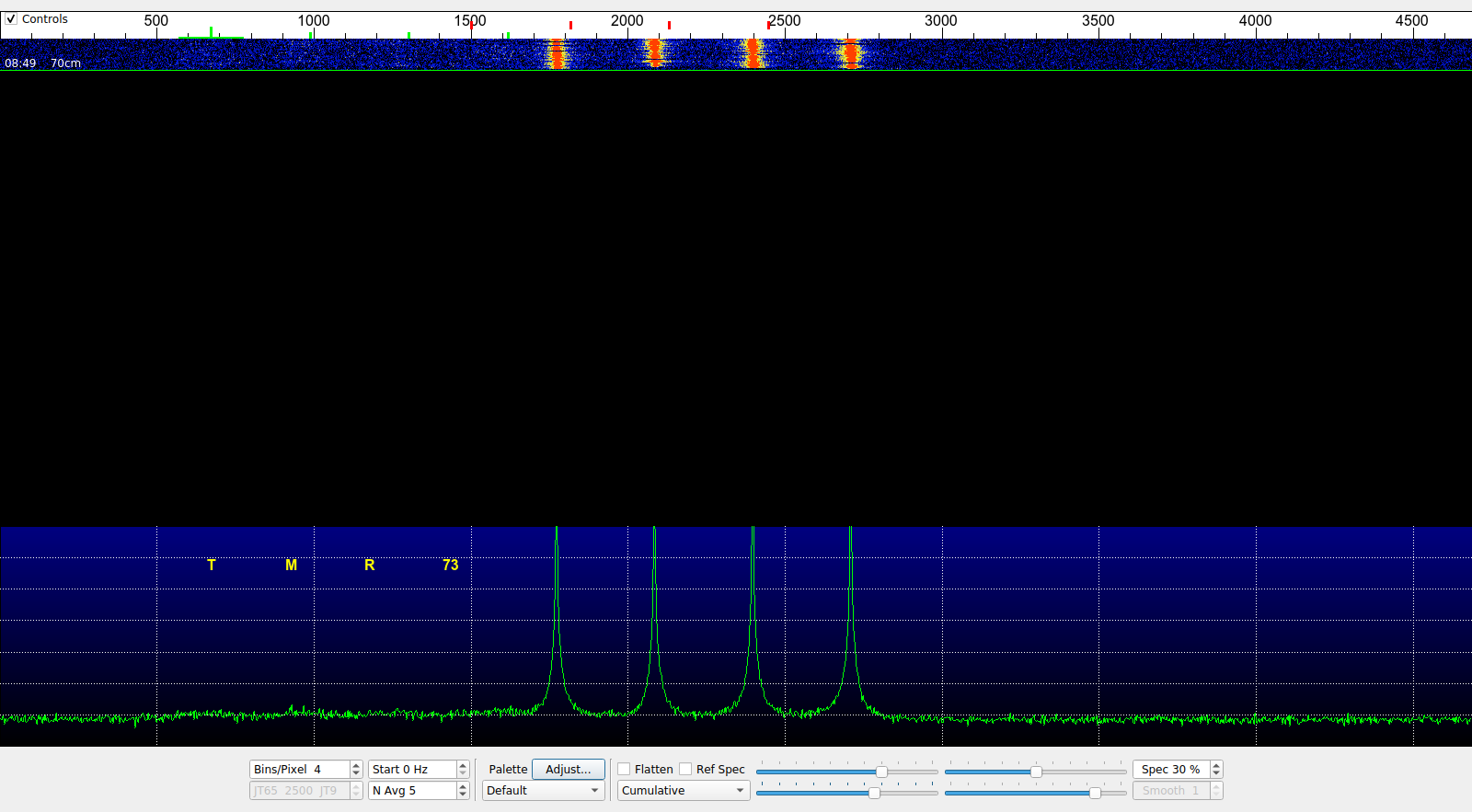
The only transmission that I have managed to decode was made at 18:11 UTC. The two screenshots below show WSJT-X decoding the WAV file extracted from the recording.
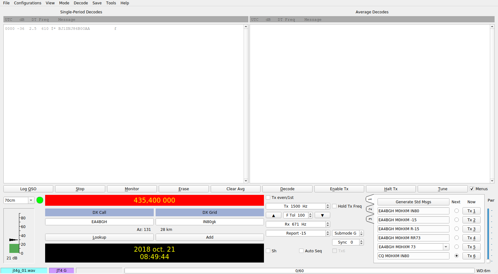
Note the direct signal with a lowest tone at 1800Hz. The reflected signal is very faint, with a lowest tone at 700Hz. The Doppler spread of the reflected signal is large, approximately 200Hz, although it is difficult to judge from the spectrum.
When the WAV file is created, I also compensate for a linear frequency drift of 25Hz per minute due to Doppler, but this is not essential to obtain a valid decode.
The WAV file that produces a decode can be downloaded here. This file can be opened directly by WSJT-X.
Thank you for putting together such an interesting analysis!
I am perplexed by two issues:
#1, if you had not specified in the narrative (and screen shot) that the Moonbounce signal was at the 700 Hz mark, I would have had no idea to set WSJTx on that RX frequency. I don’t see it visually… how did you know it was at 700 Hz?
#2, initially I was not able to decode anything from your sample .WAV file. However, after duplicating ALL of your settings in WSJTx, I was successful. The culprit turned out to be the “F Tol” setting. Perhaps wrongly, I had always assumed that there was a benefit to a larger number in this setting. By chance do you know why an “F Tol” value of 100 works in this example but higher values do not? (… thinking I should start setting “F Tol” to 100 for ‘live’ DSLWP sessions!?!?)
Thanks!
-Scott, K4KDR
Hi Scott,
#1. Once you know it’s there, the signal is barely visible in the WSJT-X waterfall (maybe it’s easier to see it in the spectrum). Using inspectrum (or in the waterfall made by Cees from the recording), it is slightly easier to see it. I tried to tweak the WSJT-X waterfall parameters to see it better, but this is the best I could get.
However, I sort of cheated. I took note of the frequency difference between the GMSK direct signal and its lunar reflection, because the reflected GMSK signal is easier to see than the reflected JT4G signal. With this information, I can find the reflected JT4G signal, since the frequency difference with the JT4G direct signal must be the same.
#2. This is a very good question, and to solve it one would need to know the details of the JT4 decoding algorithm (I only know some generalities). I expect that the problem with setting a higher frequency tolerance is that the decoder selects an incorrect frequency for decoding, and so decoding fails. Since JT4 is only decoded at a single frequency (the one detected in the first step), then you don’t get the decode. Therefore, selecting a lower frequency tolerance makes the decoder less likely to making this sort of mistakes in the first step. Ideally, you can set the frequency tolerance very low if you know were your signal is going to appear.