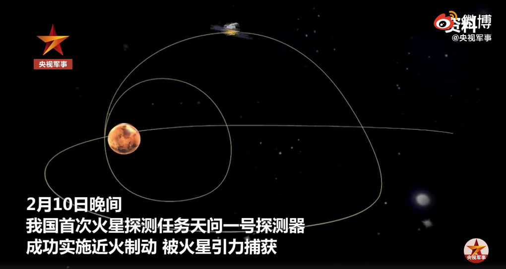
Today, the Chinese media published a short piece of news stating that tomorrow, 2021-02-15, Tiawen-1 will make make a plane change to a polar orbit. The post is accompanied by an short video, which includes an animation depicting the manoeuvre. A screenshot of the video is shown below. As the spacecraft arrives to apoapsis, it effects a plane change into an ascending polar orbit.
This is a good moment to review the maths behind a plane change manoeuvre and compute what the manoeuvre will look like.
Basically, a plane change involves changing the direction of the specific angular momentum vector \(h = r \times v\), which is one of the conserved quantities of a Keplerian orbit, and is orthogonal to the orbital plane. Understanding a plane change in terms of the angular momentum shows that it’s best to perform the plane change at apoapsis, when \(r\) is largest, and so the same thrust force produces more torque, due to the larger lever arm.
If we perform a plane change at a certain point \(r\) along the orbit, the final angular momentum \(h_1 = r \times v_1\) will be orthogonal to \(r\). In other words, \(r\) must still lie in the final orbital plane. So the only thing that we can do is rotate the orbital plane along the axis \(r\). For a plane change at the apoapsis, we are limited to swinging the orbital plane along the line of apsides.
If we denote initial quantities with the subscript 0 and final quantities with the subscript 1, we have \(h_1 – h_0 = r \times (v_1 – v_0)\). For a plane change at apoapsis, \(r\) and \(v\) are orthogonal, and so we see that the change in angular momentum \(h_1 – h_0\) and the delta-V \(\Delta v = v_1 – v_0\) are related by a factor of \(\|r\|\) and a 90º rotation. Thus, it is possible to plan the manoeuvre with angular momentums, and then easily translate the result into delta-V. For the general case in which \(r\) and \(v\) are not orthogonal, a similar procedure can be applied, since we are only interested in the projection of \(v\) onto the plane orthogonal to \(r\).
Denoting by \(\alpha\) the angle between \(h_0\) and \(h_1\) and assuming that we only want to change the direction of the angular momentum but not its magnitude, we have\[\|h_1-h_0\| = \|h_0\| \sqrt{2 (1-\cos \alpha)}.\]
In order to compute the angle \(\alpha\), let us consider the following geometric scenario. Denote by \(\delta\) the angle between a certain vector \(h\) and the \(xy\)-plane, and by \(\beta\) the angle between \(r\) and the \(z\)-axis. Let us consider the rotation of the vector \(h\) about the axis given by \(r\), and let \(\gamma\) be the angle of the rotation that brings \(h\) into the \(xy\)-plane. Then we have\[\sin \delta = \sin \gamma \sin \beta.\]Applying this to \(h = h_0\), we see that \(\delta = \pi/2 – i_0\), where \(i_0\) denotes the initial inclination. Thus,\[\cos i_0 = \sin \gamma_0 \sin \beta.\]We can write the same equation for the final angular momentum \(h_1\), and since in this case we are interested in achieving a polar orbit with \(i_1 = \pi/2\), we obtain\[0 = \sin \gamma_1 \sin \beta,\]which implies \(\gamma_1 = 0\). In the general case in which the final orbit is not polar the calculations are more involved, but the same procedure can be used.
Now, the angle \(\alpha\) is basically \(|\gamma_0 – \gamma_1|\) (some care should be taken with the signs here), because \(\gamma_0\) and \(\gamma_1\) are rotations of the vectors \(h_0\) and \(h_1\) on the plane orthogonal to \(r\), on which both of these vectors lie, and so that the result of these rotations gives the same vector (namely the intersection of the plane orthogonal to \(r\) and the \(xy\)-plane). Therefore, a rotation of angle \(\pm|\gamma_0 – \gamma_1|\) transforms \(h_0\) in \(h_1\). In the case of a final polar orbit we have\[\sin \alpha = \frac{\cos i_0}{\sin \beta}.\]
A more direct method of calculation of the required delta-V is given in the Wikipedia article about plane change manoeuvres, but I think that this way of working can give more geometric insight, even if it is a longer procedure.
Let us now work with the orbit of Tianwen-1. For this planning exercise, I have started with my planning of the Mars orbit insertion burn. The initial state vector comes from before the burn (and was given in this post). I have adjusted the start of the burn to 11:52:55 UTC to match the timing we saw in AMSAT-DL’s livestream from Bochum (taking into account 641 seconds of light-time delay), and the duration of the burn to 888 seconds so as to give an orbital period very close to 10 days, as given in this official statement from CNSA about the success of the Mars orbit insertion. The period given there is certainly rounded rather than exact, but for this planning exercise we don’t need the exact period, since we are more interested in computing the required burn rather than in knowing exactly when is the apoapsis passage.
In fact, an error in the orbital period will give a proportional error in the apoapsis radius, and hence in the required delta-V, but all the remaining geometrical parameters will be very similar. It is important to remark that even though burning exactly at apoapsis minimizes the delta-V, the radius \(r\) changes quite slowly around apoapsis, so it is possible that the burn will happen several hours away from apoapsis, favouring other conditions such as groundstation availability. For this manoeuvre, unlike for the Mars orbit injection, timing is not very critical, so it is difficult to be sure of exactly when it will be done.
In GMAT, we can see that after Mars orbit insertion the angular momentum is 17658 km²/s, and the inclination is 11 degrees (matching the inclination of the incoming hyperbolic orbit). We still need to compute the angle \(\beta\) between the vector \(r\) at apoapsis and the \(z\)-axis. This can be done by using the apoapsis radius, which is 182602 km, and the \(z\) component of the position at apoapsis, which is -31427 km. With these values we get \(\beta = 100\ \mathrm{deg}\). Using the formula above we get that the angle \(\alpha\) that the angular momentum needs to rotate is 85.24 degrees. Note that this angle is larger than the change in inclination, which is 79 degrees. This always happens when the burn is not at the line of nodes.
The fact that \(\alpha\) is smaller than 90 degrees can justify that the plane change will be made in an ascending direction. A plane change to the same polar orbit but in a descending direction could be done by using \(-h_1\) instead of \(h_1\). In that case the angle \(\alpha\) would be 94.76 degrees, and so the burn will be slightly more expensive.
Using one of the formulas given above, we get\[\|h_1 – h_0\| = 1.354 \|h_0\| = 23916\ \mathrm{km}^2/\mathrm{s}.\]Dividing by the apoapsis radius, we get\[\|\Delta v\| = \|h_1 – h_0\|/\|r\| = 130.97\ \mathrm{m}/\mathrm{s}.\]
Now that we know the magnitude of the delta-V, the next question is how to write the delta-V vector. Usually these are written in a VNB coordinate frame. In this case, the delta-V will lie in the VN-plane, since \(v\) and \(r\) are orthogonal. Knowing that the angle between \(v_0\) and \(v_1\) is \(\alpha\) and that the unit vector \(V\) of the VNB frame points along \(v_0\), we see that\[v_1 = (\cos \alpha V + \sin \alpha N)\|v_0\|,\]so that\[v_1 – v_0 = ((\cos \alpha – 1) V + \sin \alpha N)\|v_0\|.\]
For Tianwen-1, we have \(\|v_0\| = 93.7\ \mathrm{m}/\mathrm{s}\), so the (V,N) coordinates of \(\Delta v\) are (-88.69, 96.37) m/s. Plugging these numbers as an impulse burn at apoapsis in GMAT, we see that the calculations are correct and the inclination of the resulting orbit is very close to 90 degrees, while the magnitude of the angular momentum has been maintained. The two figures below show the results of this impulse burn propagated to the next periapsis.
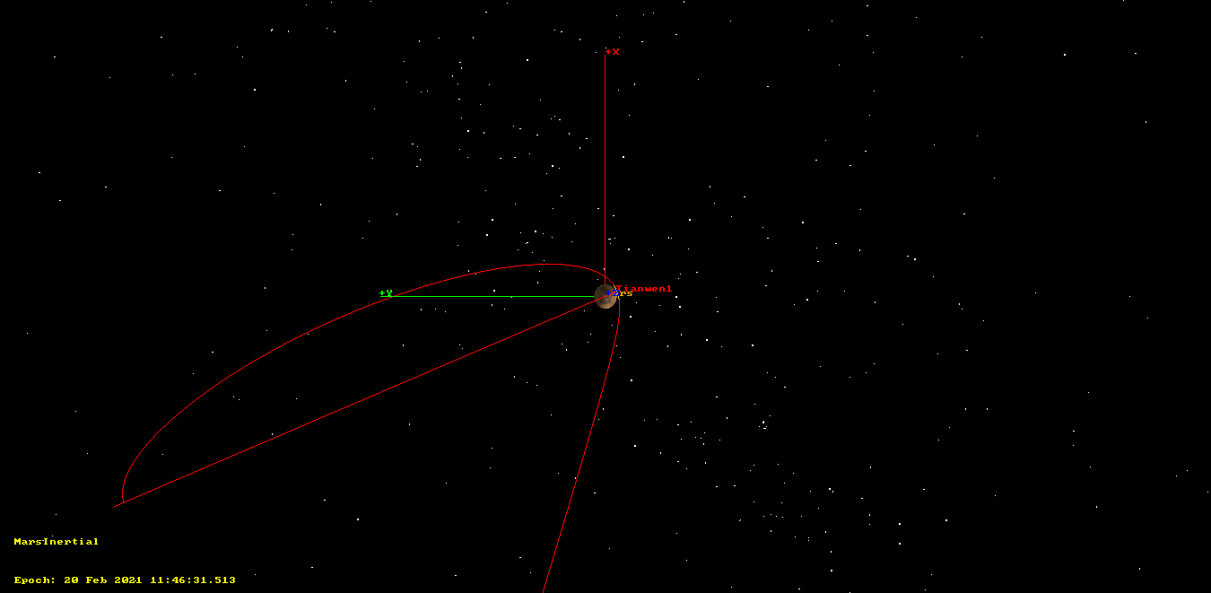
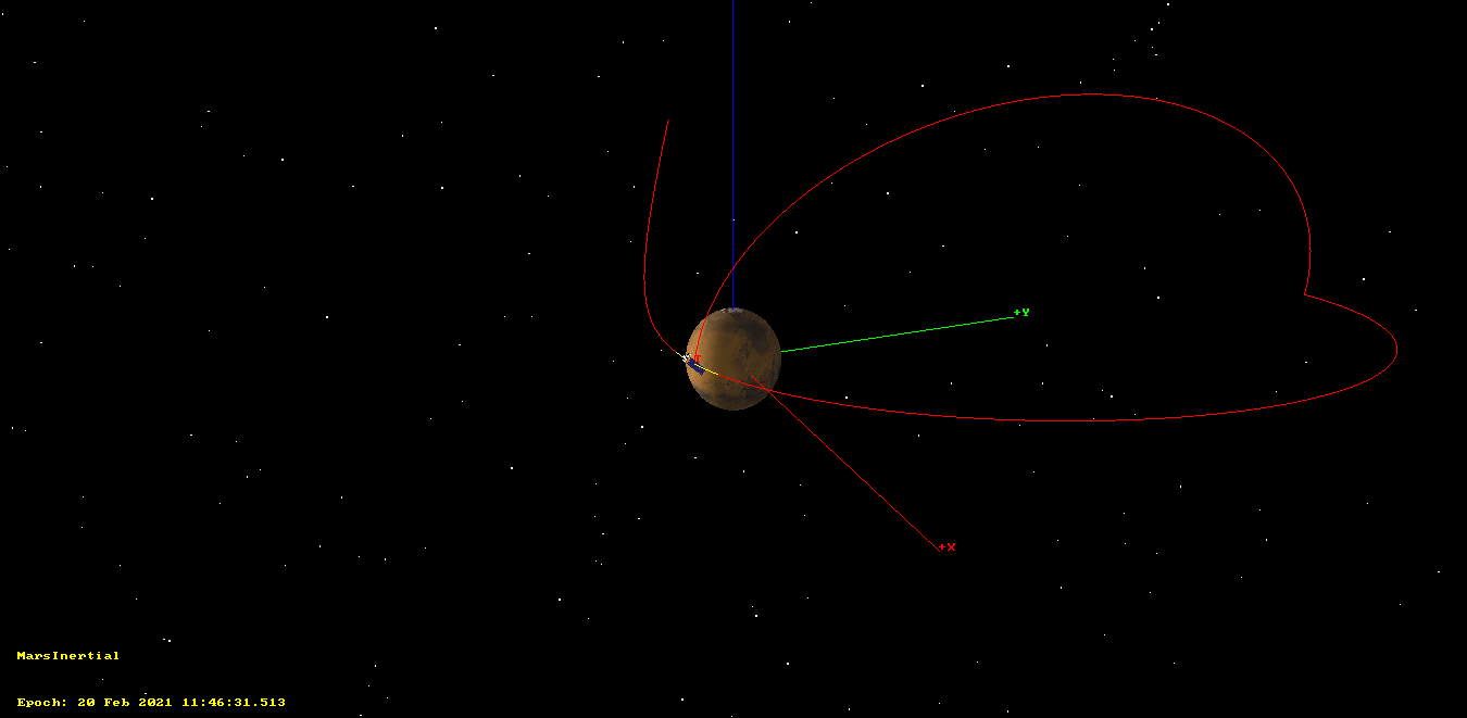
To compute the burn time \(T\) for a finite burn that achieves the required delta-V, we use\[T = \frac{v_e m_0}{F} (1 – \exp(-\|\Delta v\|/v_e)),\]where \(v_e = 3154\ \mathrm{m}/\mathrm{s}\) is the exhaust speed of the thrusters, and the thrust \(F\) is 3kN. This gives 153.12 seconds. To enter the finite burn in GMAT it is also necessary to compute the direction of the delta-V vector in inertial coordinates. The VNB frame can’t be used, since it will change throughout the burn. This is easy to do, by using the values of \(r\) and \(v_0\) in the Mars inertial frame in order to compute the coordinates of V and N in this frame. The resulting orbit after performing this burn has almost the same angular momentum as the original orbit and an inclination close to 90 degrees, showing that our calculations are correct.
The figures below show the finite burn. They are almost identical to those of the impulse burn. The finite burn is marked with a yellow trace, but this can’t be seen because the spacecraft travels a short distance during the burn, in contrast to the Mars orbit insertion, where the velocity was much higher.


This burn will spend 145.6 kg of fuel. According to our estimates for the fuel spent throughout the mission, only 45 kg of fuel will remain afterwards. This seems a bit low, so it is possible that our estimates have been too pessimistic, and the amount of remaining fuel will be closer to 100 kg.
Planning ahead, according to this article, the apoapsis will then be lowered to achieve a parking orbit with period of around 2 days, from which the lander will be released. Finally, the orbiter will move to the remote sensing orbit, which is an 8 hour circular polar orbit. Note that part of the information in that article seems outdated. It mentions that “Because the landing area is selected in the low-latitude zone”. However, the landing location is expected to be Utopia Planitia, at 46.7º N latitude. Therefore, in the article the parking orbit is depicted as low inclination, whereas for a landing at 46.7º N a polar orbit is better. Moreover, performing the plane change at the apoapsis of the capture orbit is less expensive than if it is performed later in the mission, with a smaller apoapsis radius.
With this in mind, the manoeuvres that remain in the mission can be accomplished without expending too much fuel. Even 45 kg of fuel would give 41.5 m/s of delta-V to the full dry mass of the spacecraft, according to the rocket equation. Additionally, at some point the lander will separate, substantially decreasing the mass.
It is possible (but no official information supports this idea) that the mission will use aerobraking as an inexpensive way to lower the apoapsis. In this case it makes sense to adjust the periapsis radius (i.e., to lower it in order to have significant drag) at the same time that the plane change is done. This amounts to making \(\|h_1\|\) a little smaller than \(\|h_0\|\). Putting \(\lambda = \|h_1\|/\|h_0\|\), we have\[\|h_1-h_0\|^2 = \|h_0\|^2 (1 + \lambda^2 – 2\lambda \cos \alpha) = \|h_0\|^2\varphi(\lambda).\]The function \(\varphi(\lambda)\) is increasing in \(\lambda\) for \(\lambda \geq \cos \alpha\). This means that a small decrease in periapsis in fact needs less delta-V than if the angular momentum was to be maintained.
The GMAT script used for the calculations in this post can be found here.
Update 2021-02-15 09:45 UTC: Apparently in our fuel calculations we had overestimated the dry mass of the spacecraft in about 1000 kg, and hence underestimated the amount of fuel at launch in nearly 1000 kg. This report gives a dry mass of 2500 kg (we used 3390 kg) and 2500 kg of fuel (we used 1530 kg). Thanks to 仙贝的红茶 for mentioning the report. Jonathan McDowell gave a launch mass of 4920 kg. Therefore, it seems that the spacecraft would have at least 900 kg more fuel than what I have calculated in this post and in previous tweets. With this in mind, the spacecraft has plenty of fuel left and aerobraking no longer seems a reasonable idea.
Wikipedia includes a mission planning image that seems more up to date than the article I have cited. According to that image, the inclination of the polar orbit would be 86.9 degrees, rather than the 90 degrees that I used in this post. The periapsis would be lowered to 265 km height at the same time that the plane change is performed. Next, the apoapsis would be lowered to give a 265 x 60000 km reconnaissance orbit. From that orbit the lander would be released around May or June.
100kg fuel remain?Will it be too low?What is your preset total propellant?Officials now say the orbiter has a total of 2500kg of fuel.
Hi Phil, we estimated only 1530 kg of fuel. I have reviewed the numbers and can’t now find our sources for the dry masses of the orbiter and lander, but they were clearly too high. I have put a short update to the post, since it seems credible that fuel masses are perhaps 900 kg larger than what I said.
thanks for your work!