In a previous post I talked about how the high data rate signal of Tianwen-1 can be used to replay recorded telemetry. I did an analysis of the telemetry transmitted over the high speed data signal on 2020-07-30 and showed how to interpret the ADCS data, but left the detailed description of the modulation and coding for a future post.
Here I will talk about the modulation and coding, and how the signal switches from the ordinary low rate telemetry to the high speed signal. I also give GNU Radio decoder flowgraphs, tianwen1_hsd.grc, which works with the 8192 bit frames, and tianwen1_hsd_shortframes.grc, which works with the 2048 bit short frames.
The Tianwen-1 high rate modulation is suppressed carrier QPSK at 2.048Mbaud. The coding is concatenated CCSDS frames, as described in the TM Synchronization and Channel Coding blue book. Interestingly, the convolutional code doesn’t include the inverter in the second branch (depicted as a triangle in the figure below).
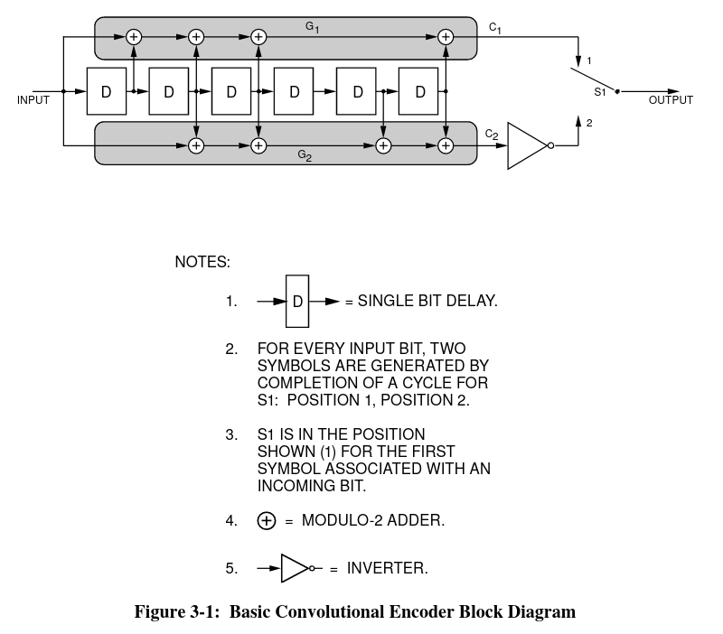
This inverter is mainly intended to improve the bit transitions for BPSK, and it is not of so much use for QPSK. I’m not sure if I’m reading the CCSDS documents correctly, but I understand that it is also recommended to use the inverter for QPSK. The low rate telemetry (which is residual carrier modulation with a BPSK-modulated subcarrier) does use the inverter.
The frame size is, counting the 32 bit syncword and the Reed-Solomon parity check bytes, either 2048 bits or 8192 bits. The 2048 bit frame size is identical to the one used for the low rate telemetry: a single (252,220) Reed-Solomon codeword is used. For the 8192 bit frames we have four interleaved (255,223) Reed-Solomon codewords, giving frames of 1020 bytes.
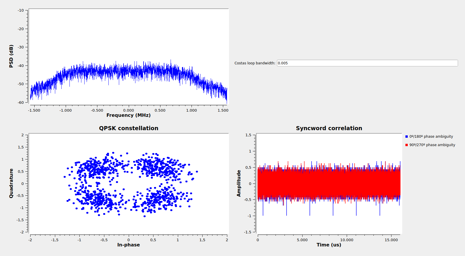
The GNU Radio decoder flowgraph for the high speed data can be seen below. It is has a typical QPSK demodulator using a polyphase RRC filter and maximum likelihood time error detector, together with a Costas loop. After demodulation, two Viterbi decoders are run in parallel to account for a 90º phase ambiguity. After Viterbi decoding, we might still get either the corrected bitstream or the inverted bitstream, so syncword detection for both is run in parallel.
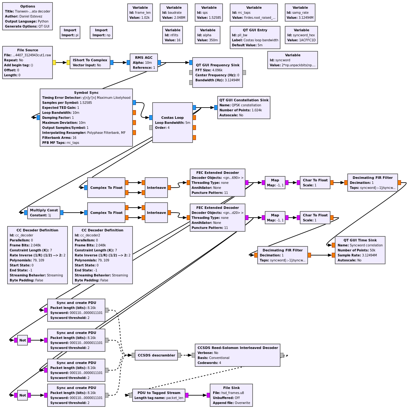
The decoder shows the spectrum of the signal, the constellation and the syncword correlation. Here we can see the syncword marking the start of a few frames. In this case, there is a 180º phase error in the Costas loop, since the syncwords are present in the 0º/180º Viterbi decoder branch and are inverted.
I have been testing the decoder with a recording made by Paul Marsh M0EYT on 2020-07-30 00:35 UTC, when the spacecraft was already 2.1 million km away from Earth. Adjusting the Costas loop bandwidth for good results was not so easy. With a suppressed carrier QPSK modulation the loop doesn’t work well with low SNR, due to the squaring losses. Probably the Chinese DSN runs the spacecraft transponder in a two-way coherent mode when downlinking high speed data, and so they can reduce the loop bandwidth.
The sequence of steps to enable the high speed data transmission is interesting. Here I summarise it using waterfall plots from the recording obtained with inspectrum. We start with the ordinary low rate telemetry downlink in the left of the figure below. At some point a telecommand is received (this can be seen in the middle of the figure, looped back on the phase modulated on the downlink carrier) and the downlink frequency changes.
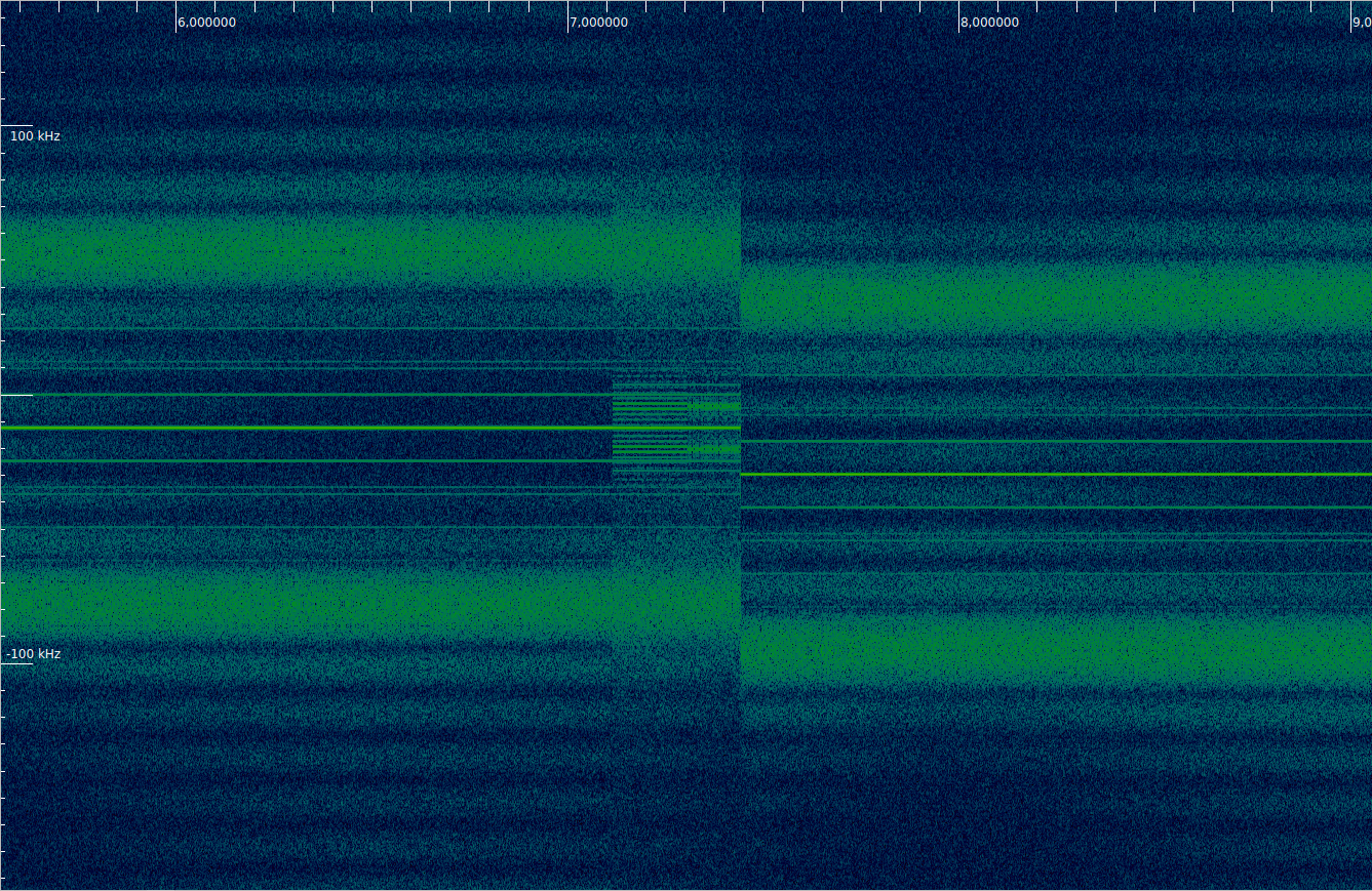
The low rate downlink continues on the new frequency until a second telecommand is received. Then the modulation changes to suppressed carrier QPSK. The baudrate of this new modulation is 8192baud and it is apparent from the spectrum that the waveform is unfiltered. I haven’t figured out all the details about this narrowband QPSK signal yet. Telecommands are not looped back with this modulation, so it is not obvious if any additional commands are received.
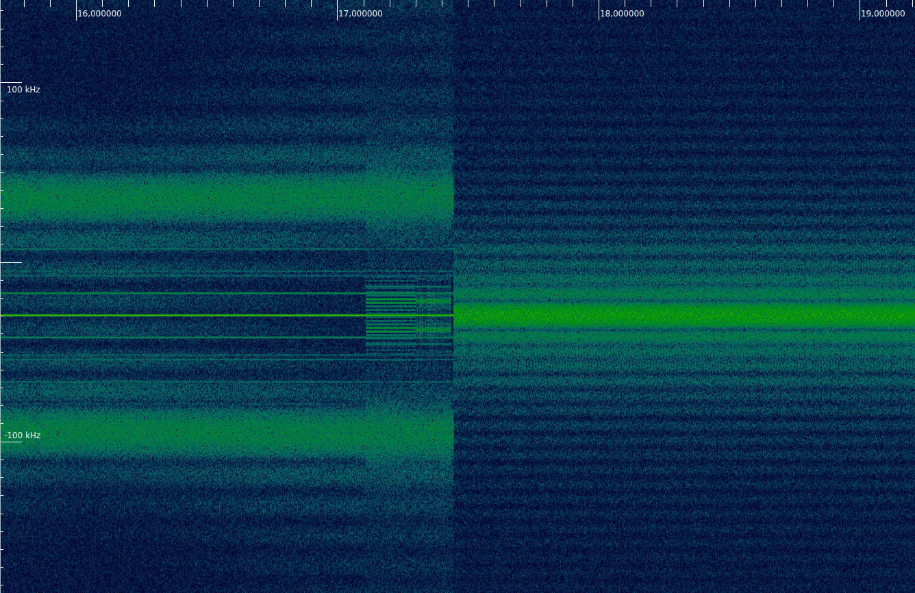
Next the signal changes to the high rate 2.048Mbaud QPSK modulation, using 2048 bit frames. Here only idle frames are sent (see below), so there are a number of spectral lines, since we are quite zoomed in on the spectrum.

Later, the signal changes to 8192 bit frames, while still transmitting idle frames. We see that the appearance of the spectral lines changes. The keen reader might also be able to spot some thin vertical lines that appear every second (click on the image to view in full size). These correspond to non-idle real-time telemetry frames that are sent each second. Each of these frames takes 4ms to transmit.
Finally the idle frames give turn to the useful data, which in this case is the telemetry replay analysed in this post. After all the replay has been transmitted, the idle frames come again. All this is done using 8192 bit frames.
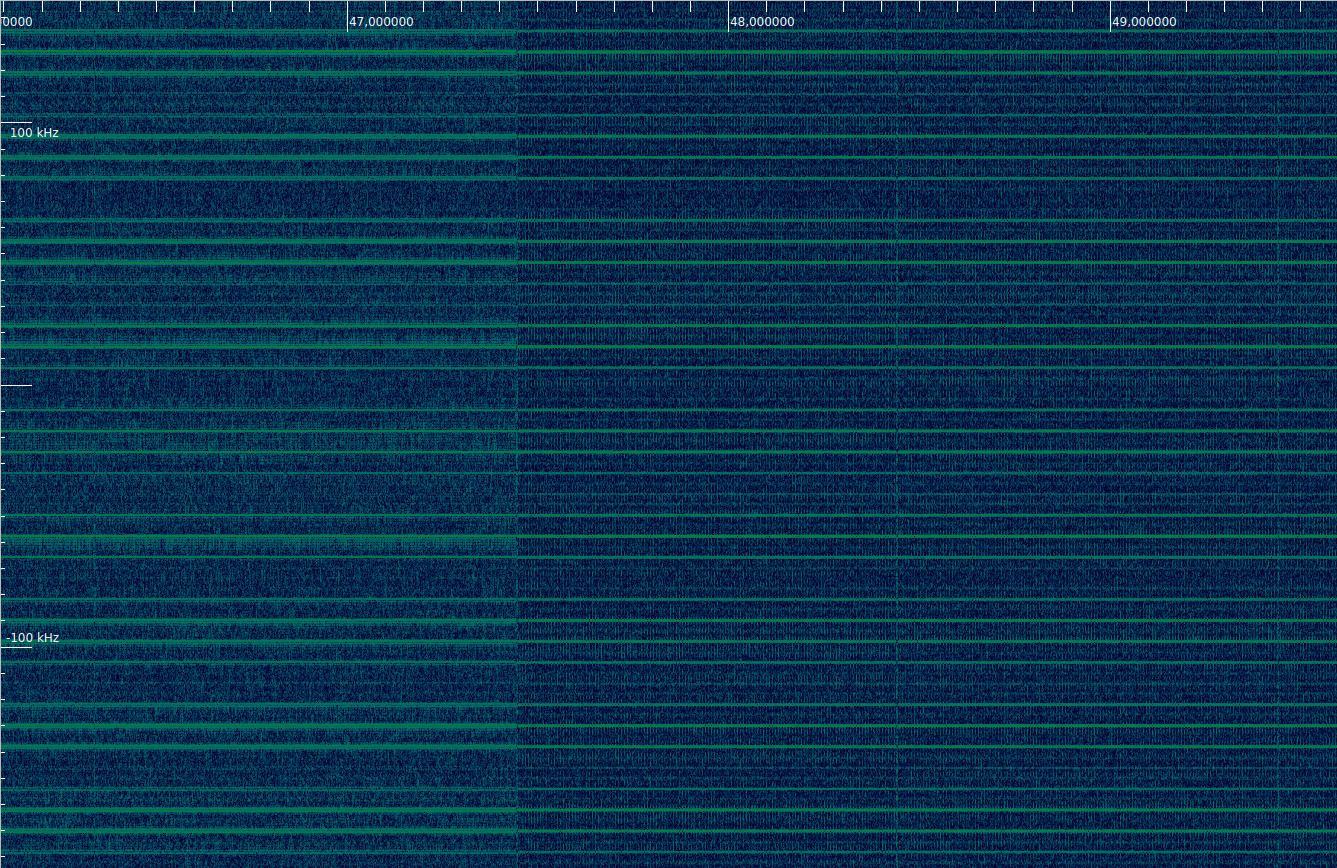
The difference between idle frames and data is also clearly visible when the spectrum is zoomed out. Note that the CCSDS scrambler is always used, so the spectral lines appear because all the idle frames are very similar (only the virtual channel frame count field and Reed-Solomon bytes change), so the signal is very close to a 4ms-periodic signal. To improve this, some missions have used an LFSR to fill the payload of idle frames.

During the transmission of the 2048 bit frames with the 2.048Mbaud QPSK signal, virtual channels 1 and 3 are used, in a similar way to the 8192 bit frames transmission, which was described in a previous post. However, there are also some spurious frames that happen when the transmission changes to 8192 bit frames. The short frame (2048 bit) decoder happily takes the start of the 8192 bit frames and outputs frames which consist only of 0x55 bytes, thinking that it its correcting 10 Reed-Solomon byte errors. When these are interpreted as AOS frames, they seem to come from spacecraft 85, virtual channel 81.
The reason for this seemingly weird behaviour of the decoder comes from an interesting fact about Reed-Solomon codes. It turns out that if all the bytes of a codeword have the same value, then that codeword belongs to the Reed-Solomon code. This is seen more easily when understanding Reed-Solomon codes as the sequences of values of a polynomial on a finite field. This kind of constant codewords correspond to the constant polynomials.
If one interprets the Reed-Solomon codewords as the coefficients of polynomials that vanish on some prefixed elements of the field \(F\) distinct from zero and one, note that if \(F\) has \(n+1 = 2^k\) elements, then the polynomial \(x^n + 1\) vanishes for all the non-zero elements of \(F\). Therefore, if \(p(x) = x^{n-1} + x^{n-2} + \cdots + x + 1\), as \(p(x) (x+1) = x^n + 1\) we see that \(p(x)\) vanishes on all the elements of \(F\) distinct from zero and one. This implies that the codewords that have the same value in all their bytes belong to the code.
In the case of the change from the 2048 bit frames to the 8192 bit frames in the high speed data signal of Tianwen-1, what happens is that the short frame decoder gets the first 252 bytes of the 8192 bit frames. Since the data hasn’t started yet, these are idle frames and most of their bytes are 0x55. In the first 252, there are only 7 bytes which are not 0x55: the first five bytes of the AOS primary header, and two bytes in the AOS frame insert zone. Additionally, the (252, 220) shortened code used in the short frames has three padding bytes in the Reed-Solomon code which are fixed to zero. This means that, comparing with the 255 byte frame which consists of 0x55 bytes only, we have a total of 10 bytes which are in error. The Reed-Solomon decoder thus happily corrects 10 bytes (it is able to correct up to 16) and obtains a valid codeword which consists only of 0x55 bytes. Note that the corrected codeword doesn’t have zeros in the padding bytes, so a smarter decoder would reject it.
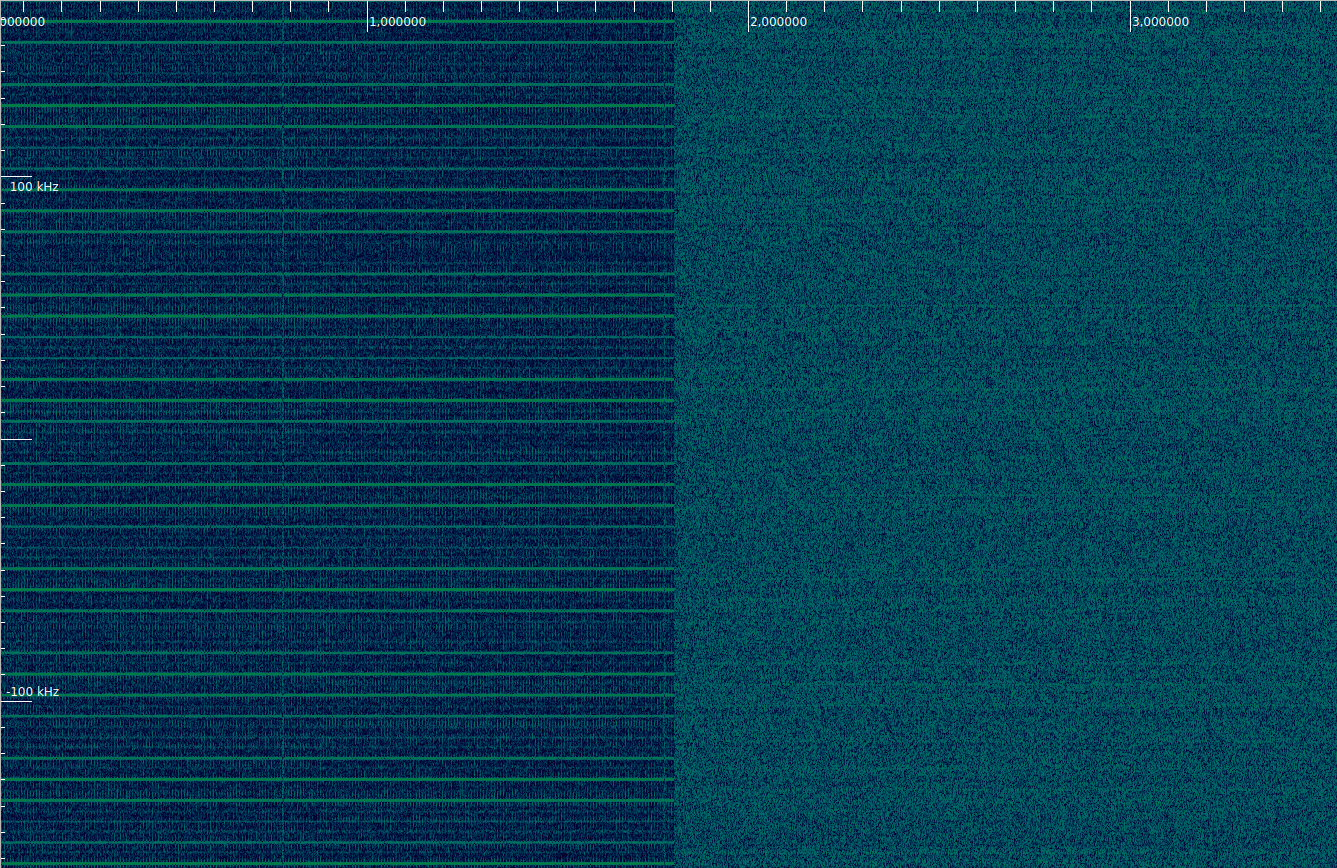
The figure below shows virtual channels used during the short frames transmission. The spurious frames produced by the Reed-Solomon decoder with the long frames are shown in the right. Every 0.5 seconds we have a telemetry frame in virtual channel 1, and the rest of the frames are idle frames in virtual channel 3.

Telemetry frames in virtual channel 1 seem identical to those used in the ordinary low rate telemetry. Idle frames in virtual channel 3 are also identical to those in the low rate telemetry signal. They use 0xaa as padding, and have the value 0x8aaa in the unknown field in the AOS insert zone (see this post). Note that the 8192 bit frames in virtual channel 3 are different: they use 0x55 as padding and have the value 0x7aaa in the unknown field.
The contents of the 8192 bit frames are described in a previous post. Since writing that post, I have discovered a bug in the implementation of the Viterbi decoder in the flowgraph. Basically, you can’t re-use the same CC Decoder Definition block for two FEC Extended Decoder blocks. After fixing this bug, I get no lost frames.
I have updated the Jupyter notebook with the analysis of the 2048 bit short frames and with the 8192 bit frames after fixing the bug in the Viterbi decoder.
The entire Tianwen-1 series has been fascinating – thank you!
Are the I/Q sample recordings available so that we can use the .GRC flowgraphs absent live data of our own?
Understand if the files are too large to share in any sane manner.
Thanks!
Hi Scott,
Sorry for the delay in replying. Most of the recordings have been done by Paul M0EYT, so maybe ask him for a sample short recording.