In a previous post, I talked about the GALI-39 amplifier kit from Minikits. Here I will describe the procedure to calibrate the S-meter in Linrad (or another SDR) using this amplifier or any other amplifier with a known NF and an uncalibrated signal source. Leif Åsbrink has a youtube video where he speaks about the calibration of the S-meter in Linrad. However, he doesn’t use an amplifier, so I will be following a slightly different procedure.
The equipment I have calibrated with this procedure is the following: I have an FT-817ND with a G4HUP PAT board that taps off the IF before the crystal filter and a FUNcube Dongle Pro+ SDR connected to this board. I have talked about the PAT board and using Linrad as a panadapter before. The S-meter in the FT-817 is known to be not very accurate, as Ramiro EA4NZ shows, so I wanted to calibrate the S-meter in Linrad so that I can use it to give much more accurate signal reports. The main use of this equipment will be on the HF amateur bands.
If one has access to a calibrated signal generator, then calibrating the S-meter in Linrad is as easy as connecting the generator to the FT-817ND input, setting an appropriate output level on the generator, and adjusting Linrad to make it display the same signal level in the S-meter. Unfortunately, I don’t have a calibrated signal generator at hand. An amplifier with a known NF and an uncalibrated signal source can be used instead. For the amplifier, I used the GALI-39 kit from Minikits, but any other suitable Minicircuits MMIC amplifier can be used. As a signal source source I used a crystal oscillator that I built from some parts I had lying around.
I had a 4.433MHz crystal, so I built an oscillator for this frequency. As I wanted to do the calibration for the HF bands, in principle, any crystal for an HF frequency would suffice. This assumes that the gain of the IF of the FT-817ND is roughly the same on all the HF bands. This may or may not be true (perhaps I will be testing this in the future). A better procedure would be to use a crystal of a suitable frequency for each band that needs to be calibrated. Then, a separate calibration can be done for each band. However, this is a much longer process, requires to use different settings of Linrad for each band, and, in the end, may not be worth the extra effort.
To build the crystal oscillator, I followed more or less the design of the Norcal S9 signal generator. This is a kit that uses a low level crystal oscillator and some attenuators to generate an S9 (-73dBm) or S1 (-107dBm) signal. I built mine to generate an S9 signal, but when performing the calibration I found the value to be quite far from S9 (although this is not surprising, since I didn’t pay much attention to component tolerances). Another similar design that can be used is the Elecraft XG2. This is probably more accurate and a bit more expensive to build than the Norcal kit, as it uses a Zener diode reference instead of an LED as a voltage reference for the oscillator.
The important thing about the oscillator to be used is that is signal level is stable. The value of the signal level is not important, as long as it is within reasonable margins to avoid saturation or leakage. Many other types of signal generators can be used. For instance, when I get to build my QRP-Labs OCXO/Si5351A kit (which incidentally arrived today), I can use the Si5351A synthesizer included in the kit.
The first step in the calibration procedure is to measure the signal level of the oscillator. This can be derived from the NF of the GALI-39 and the SNR of the signal when it is received through the amplifier. For this step, the GALI-39 amplifier should be connected to an SDR receiver. Any SDR receiver can be used, but it helps that its NF is as low as possible, so that the NF of the total receive chain is dominated by the NF of the GALI-39. I intended to connect my FUNCube Dongle Pro+ directly to the GALI-39, but I found that its NF at 4MHz was quite large. The NF of the FT-817ND-FUNCube Dongle Pro+ combination was much better, so I just connected the GALI-39 amplifier to my usual FT-817ND-Funcube Dongle Pro+ setup. To improve the NF, I turned off the IPO function in the FT-817ND (that means that the preamplifier gets turned on). However, I turned off the LNA of the dongle to avoid saturation in later steps. Being later in the chain, the LNA of the dongle doesn’t make much difference to the total NF.
To find whether the NF of the complete receive system is dominated by the NF of the GALI-39, I used a method I’ve described before. The idea is to measure the drop in the noise floor when the GALI-39 is switched off. Ideally, we would like to have a large drop. Therefore, the way to find which receiver settings give a lower NF (such as turning off the IPO) is turning the GALI-39 on and off while changing the settings to see which give the largest drop. The following figures show the noise floor in Linrad first with the GALI-39 on and then off.
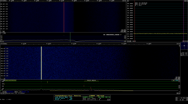
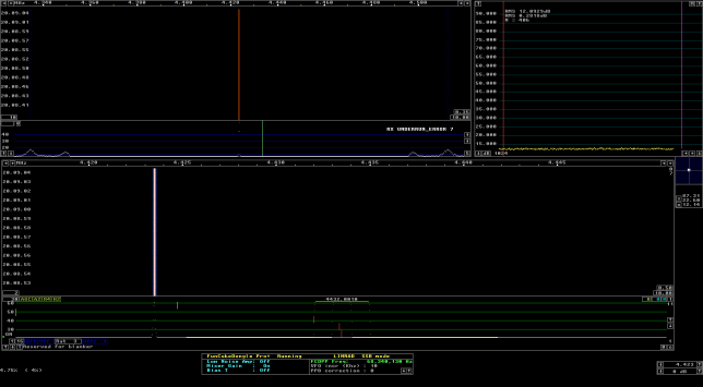
The noise floor is 26.06dB with the GALI-39 on and 12.09dB with the GALI-39 off. That’s a 13.97dB drop in the noise floor. Using the formula for the estimation of the NF contribution, we see that the NF of the complete receive system is just the NF of the GALI-39 up to 0.18dB. There are some performance curves for the GALI-39, but they don’t give much information in the HF region (the first tick in the graph is 200MHz). From the graph, it seems that a NF of 2.25dB is a good approximation for frequencies up to 1GHz. Therefore, we’ll say that the NF of our receive system is 2.25dB (give or take about 0.2dB).
The next step is to connect the signal source to the GALI-39 input and measure its signal level on Linrad. The same settings for the receiver should be used in this step, but it is also important that a fixed bandwidth is used in Linrad. I used 3kHz, but 500Hz is another usual choice. In fact, I set a bandwidth of 3kHz right from the start. Therefore, the noise floor measurements done before are also in 3kHz bandwidth (if not, the noise floor with the GALI-39 on would have to be measured again).
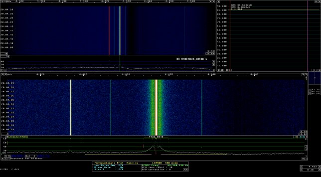
The following figure shows the signal level of the oscillator with the GALI-39 on. It is 85.58dB. The noise floor has not changed, so it is still 26.06dB in a 3kHz bandwidth. Therefore, the signal-to-noise ratio is 59.52dB. Since the GALI-39 degrades the signal-to-noise ratio by 2.25dB, that means that the signal of the oscillator is 61.77dB above the Johnson-Nyquist noise in 3kHz bandwidth. Knowing that the Johnson-Nyquist noise in 1kHz bandwidth is -144dBm, we see that it is -139.23dB in 3kHz bandwidth. Therefore, the signal level of the oscillator is -77.46dBm, which is quite off from the -73dBm it was supposed to be.
Now that we know that our signal source has a level of -77.46dBm, the procedure continues as if we were using a calibrated signal generator. The GALI-39 is removed from the receive chain and the signal source is connected directly to the FT-817ND. The receiver settings should be now the ones for which the S-meter calibration is going to be done. For me, this means IPO on (preamp off) and the LNA of the dongle off. Any change in these settings changes the gain of the receiver, so the S-meter calibration will be no longer valid. The bandwidth to be used in Linrad now is not important. Probably the easiest thing to do is to use the same Linrad settings that will be used during regular use.
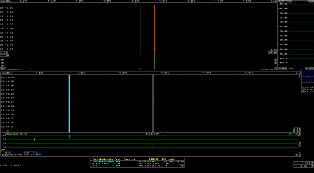
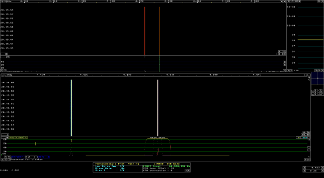
First, the dBm signal meter in Linrad has to be calibrated to read -77.46dBm on the oscillator signal. An appropriate value must be entered on the calibration box in the signal meter. I never remember which way the calibration values should go, so I just use trial and error. The following figure shows the calibration of the dBm meter.
Then, the S-meter in Linrad has to be calibrated. A signal of -77.46dBm is S8+1.54dB or S9-4.46dB, since S9 is defined as -73dBm on the HF bands (on VHF and above S9 is defined as -93dBm), and an S-unit is 6dB. Therefore, what I do to adjust the S-meter is to first set a calibration value so that the meter reads exactly S8 or S9. Then, if it is reading S8, I add or subtract 1.54 to the calibration value (once again, I never remember which way it goes, so I use trial and error) so that the reading moves above S8. If it is reading S9, I add or subtract 4.46 from the calibration value so that the reading moves below S9. I find that this method is easier and more accurate that converting -77.46dBm to S8.26 (actually I’ve never seen anybody to use fractional S-units) and try to move the reading there. The method I use works because the calibration value is in dB units, not in S-units. The following figure shows the calibration of the S-meter.
When thinking about how large is the error made when using this method of calibration, it seems that the largest contribution to the total error comes from the estimation of the NF of the GALI-39 and the complete receive system. It seems reasonable to assume that the NF is known up to about 0.5dB. The error associated with the insertion loss of the connectors needed to set everything up and other factors is probably much smaller than 0.5dB. I think that an accuracy of 1dB is more than enough to give accurate reports in S-units, so this method seems to work quite well for this application.