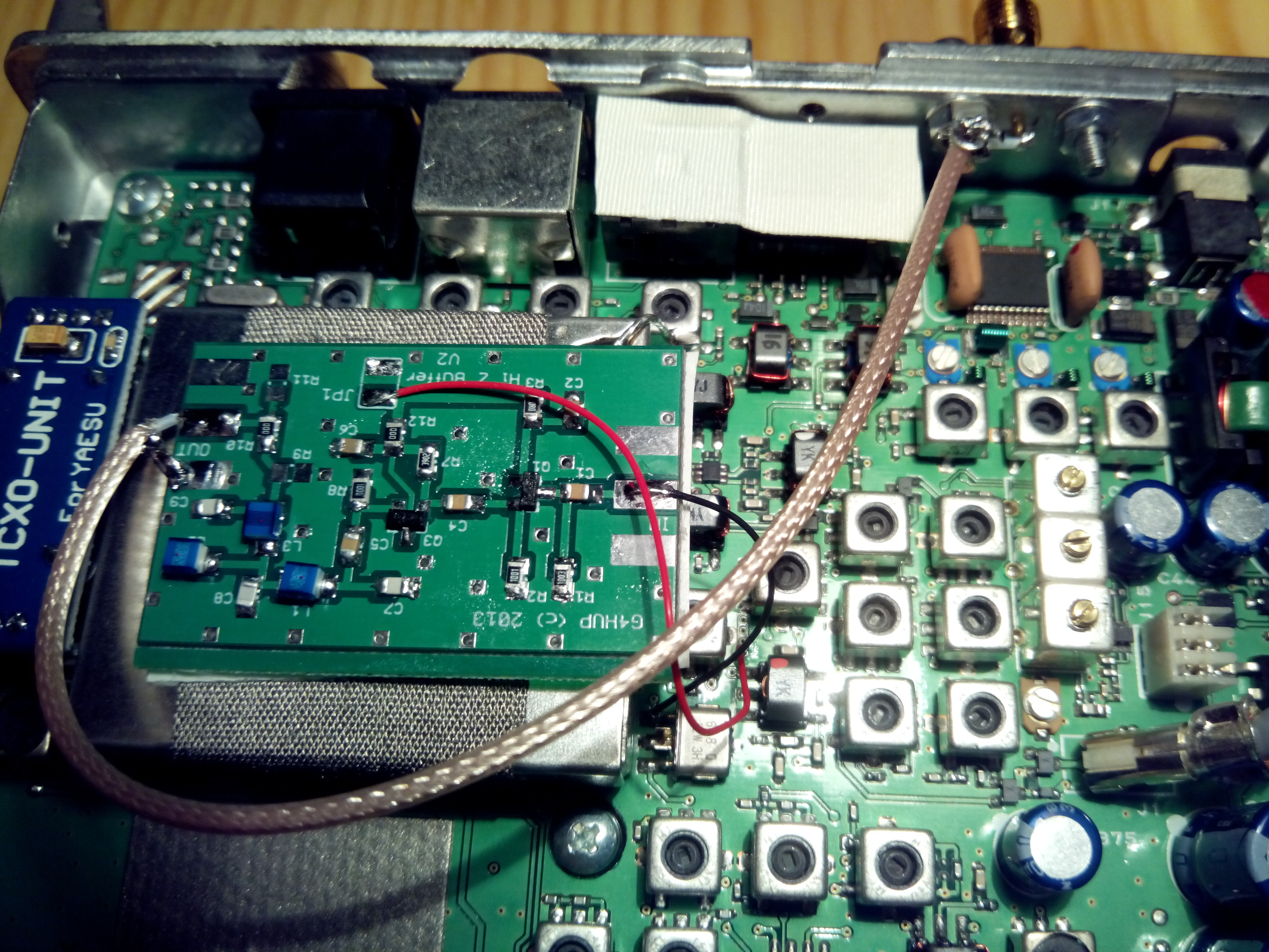
Today I’ve been installing the G4HUP PAT kit on my FT-817ND transceiver. This kit is essentially a buffer amplifier that allows one to tap the IF of a transceiver, in order to send it to an SDR. Then, the SDR can be used as a panadapter. This kit is intended as an entry level SMD project and it can be fitted to many popular amateur radio transceivers. In fact, this has been my first SMD project, and I have found it quite easy to solder using the right tools and technique.
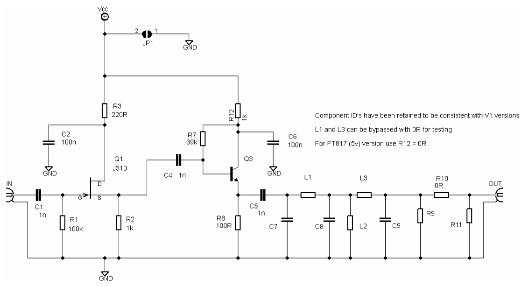
The circuit is simple. Q1 is a JFET source follower which gives a high input impedance and then Q3 is an emitter follower for impedance transformation. L1, L2, L3 and C7, C8, C9 form a low pass filter and R9, R10 and R11 are an optional resistive attenuator which can be used to reduce the signal level in case it is necessary (it is not necessary for the FT-817 and the FUNCube Dongle Pro+ or an RTLSDR). Q1 is an MMBFJ309 and Q3 is a BFS17. The values of the low pass filter components are chosen according to the IF frequency of the radio in question. The FT-817 has a 70MHz IF (actually it’s 68.33MHz), so the low pass filter cutoff frequency is about 75MHz and L1, L2, L3 are 150nH, C7, C9 are 56pF and C8 is 120pF. R9 and R11 are left unpopulated. The Vcc for the PAT board must be taken from a line which supplies voltage only during RX, so that the circuit switches off during TX. This line is called +RxB. On many base station transceivers +RxB is about 8 to 10V. However, on the FT-817 it is only 5V, so R12 should be 0R.
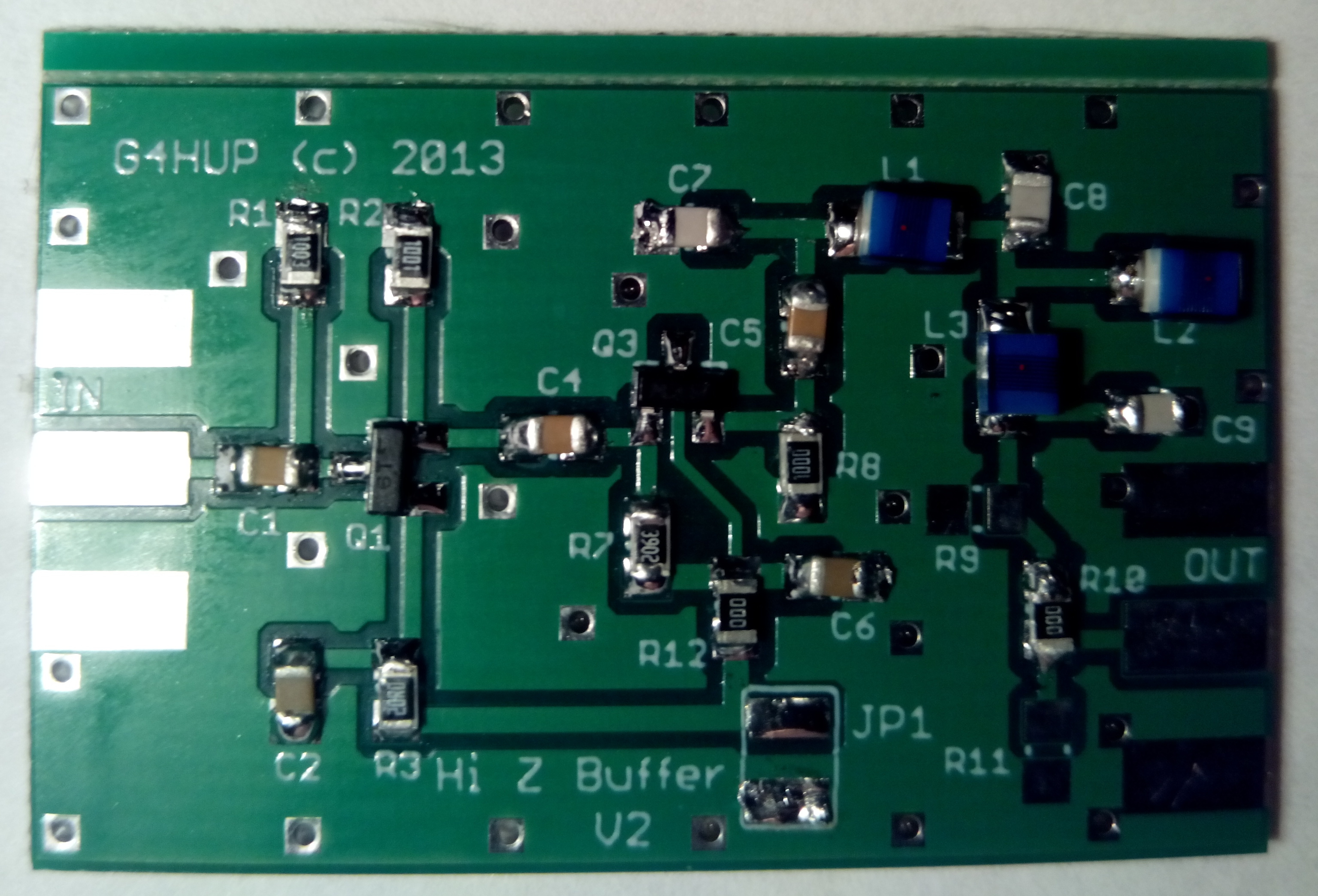
The board is neatly laid to allow for easy hand tsoldering. Everything is on the front side. The back side is just a ground plane, which is connected to the front side ground plane with several vias.
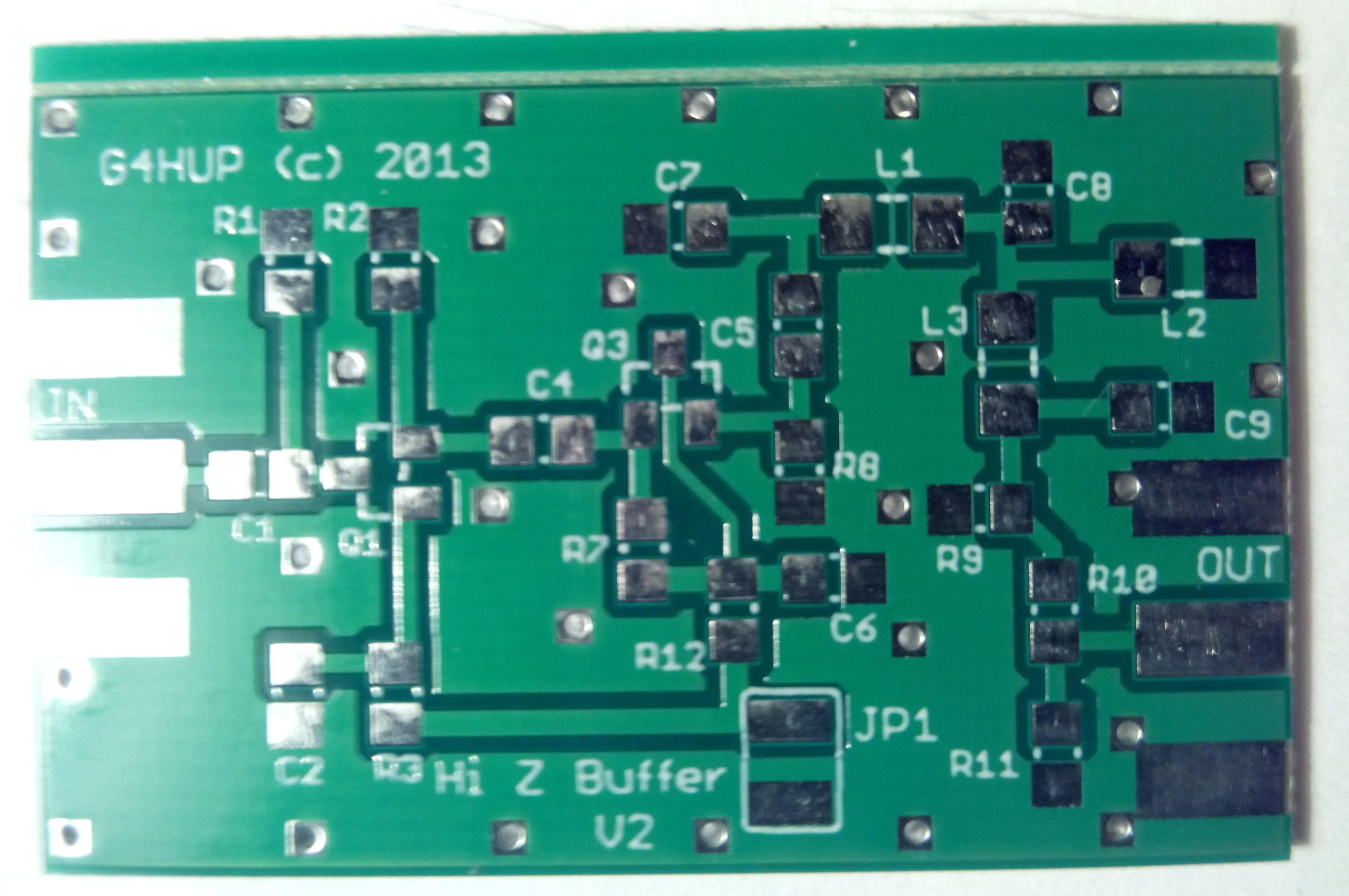
The resistors and capacitors are 0805 and the inductors are a bit larger, so they can be soldered easily. The technique is to tin one pad, then move the component onto the pad with the tweezers while the solder is molten to tack it in place and then solder the other pad. The transistors are SOT23 and the same technique can be used to solder them.
The board has to be connected to the FT-817 PCB at two points: the +RxB line and a suitable point to tap the IF off. G4HUP provides photographs of these points, but I found them slightly confusing, so it is handy to have the service manual around to locate these points. Apparently, +RxB can only be accessed on the front side of the main PCB at a single point: a via between T1006 and T1014. This is marked in the PCB schematic below. The PLL unit is the large metal can towards the back of the radio. Actually, this can is the recommended place to install the PAT board, by sticking it on top of the can with two-sided tape.

The IF can be tapped at the input of the IF crystal filter, XF1001. There is almost no filtering before this point, so this provides a large bandwidth (several MHz in my first tests). It seems to me that the instructions for the installation of the PAT board show how to tap at the output of the crystal filter (instead of the input). It is also stated there that a bandwidth of 60kHz can be obtained (which would be consistent with tapping at the output). I have tapped at the input of the filter, and I haven’t detected any problems. There are other people also tapping at the input. It would be interesting to compare the performance of tapping at the input versus tapping at the output. For me, the extra bandwidth is probably the deciding factor for tapping at the input.
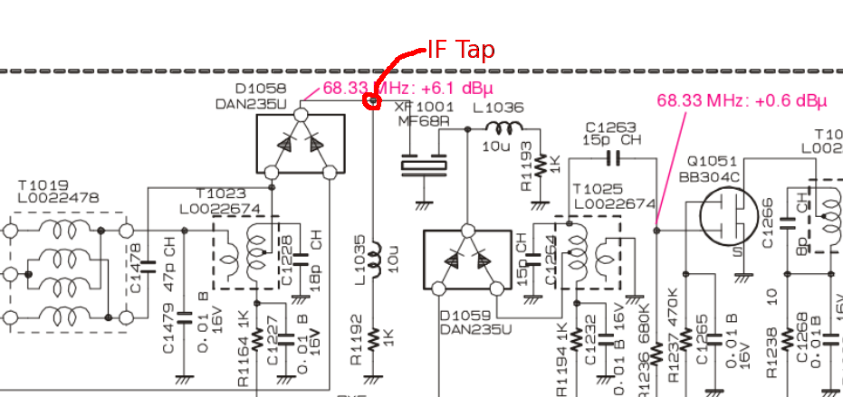
The kit comes with very fine insulated wire that can be used to tap the IF and +RxB. Indeed, it is so fine that you can insert it through the via. I found it easier to insert it in the via to fix it in place and then just solder it there. Soldering to the crystal filter is quite easy because its pins are relatively large (there’s also a via next to the pin, so the same trick may be used).

To finish the installation, the output of the PAT board must be taken to a female SMA connector installed on the back panel using RG178 coax. The back panel must be drilled to allow the installation of the connector. It is a good idea do the drilling first, before you start soldering or mounting things onto the FT-817 PCB. The instructions of the PAT board have a good description of where to install the connector, how to do the drilling safely (actually it isn’t difficult at all if you are careful) and how to solder the braid to the solder slug properly. Another nice tip that I learnt from the Hardrock 50 instructions is to use a toothpick to prepare the braid.
The wire connecting the IF tap to the board input should be as short as possible. To do the installation with short wires, I found the following procedure useful. First solder the full length wires onto the FT-817 PCB and the full length coax to the PAT board. Position the PAT board in place (don’t stick it yet to avoid damage to the tape while soldering). Cut the wires to the proper length, and then solder them onto the PAT board. Stick the PAT board in place. Then cut the coax to the proper length and solder it to the SMA connector.
When testing the board, it is important to note that the LO frequency is above the IF frequency on the FT-817, so the sidebands on the IF are inverted. Of course, this is no problem, because it can be handled by the SDR software. I’ll be using Linrad and probably an RTLSDR (to make use of the large bandwidth that is available). I still need to make several tests and to configure the software properly, but when I finish I will describe my set up in a future post.
Hi Daniel,
Have you compared tapping the IF on the OUTPUT of the filter?
Regards,
Simon M0VCP
Hi Daniel,
Have you compared tapping the IF on the OUTPUT of the filter?
Regards,
Simon
No, but other people have done it. You can find the results online. The problem with tapping after the crystal filter is that the bandwidth is about 20 or 30kHz.
Thanks Daniel.
Hello Daniel,
I trying to understand the values for the low pass filter. According to my calculations, the LC 56pF & 150nF resonate at 54 MHz. The 120pF & 150nF resonate at 34 MHz. This would cut off above 54 and below 34 MHz.
What am I missing?
I’ve just done a simulation of the filter and everything seems in order. Note that it’s actually a bandpass filter. https://twitter.com/ea4gpz/status/854078378705649665
Thanks Daniel!
Hello has anyone tried to measure the output power after the mod? I did and I found out that it decreases from 5w to 3w; I guess the input stage of the powered down pan apdapter is loading the IF stage somehow.
I regularly get 5W without problems. It doesn’t make much sense that you get a reduced TX output power, since in TX there is plenty of drive at the point where the panadapter tap is done.
hello Daniel, it is puzzling me as well, but the test does not leave space to doubts; if l key CW with the pan adapter input connected to if filter input, i can read 3w output on wattmeter and as soon as i disconnect the wire and rekey the reading goes back to 5w.
Have you tried output power in FM? Have you tried adjusting the output power with the pan adapter board connected? (see here).
Good point, Daniel, I’ll run these tests next week end!
Thank you!
Hi.
I’m a newbie and find very difficult to get the +RxB on my FT-817nd. Is there any other way to power up the PAT? Would appreciate any help!
Juan
Hi Juan, the PAT could be powered in another way, but it is important that the PAT is powered off during TX, to prevent hardware damage. Therefore, the +RxB line gives a convenient way of powering the PAT only in RX, so it is the recommended way. If you use another way you need to figure out how to cut the power off when the radio goes to TX.
Hi, just going into my FT817ND using a HupRF board. Glad I found this post re the input or output TAP debate.
I was initially following Dave’s instructions to TAP the output. You make perfect sense.
Thanks Andy GD1MIP.
Hi, can we receive on SDR receiver the FM broadcast, Air band and VHF/UHF bands with this TAP output ?
Yes. Any band you can tune to with the FT-817 will show up in the 70MHz IF that is picked up by the TAP.
Will this board work with the 818? If so are the solder locations the same?
Hi Michael, I don’t know what are the changes between the FT817ND and the FT818.
I’ve installed this item on ft818 and works but the filter is smaller then in 817 and more difficult.
I use sdr consolle and rtlsdr …818 plus 10ghz trv…if 144 Mhz.
Anyone has experience to setting sdr consolle trv??