Recently, I installed a G4HUP PAT on my FT-817ND. This is a small board which allows one to tap the IF of a conventional radio receiver to use an SDR as a panadapter (essentially, a waterfall display which shows a chunk of spectrum about the frequency tuned on the receiver). In the previous post I described the installation of the hardware. Here I will describe how I’ve set up Linrad to suit my preferences. One interesting aspect of this set up is that I’ve ended up adding a bit of code in Linrad to make it read the dial frequency of the radio using CAT and make Linrad track the frequency as one tunes around in the radio.
My G4HUP PAT is installed to tap the IF before the crystal filter, so several MHz of bandwidth are available. For this reason, I intended to use an RTLSDR as SDR receiver, instead of the FUNCube Dongle Pro+ that I use normally. Being able to get 2MHz of spectrum in the waterfall is quite nice, because not only any single amateur radio HF band can be monitored completely, but neighbouring HF broadcast stations can also be watched. In comparison, the FUNCube Dongle is just 192kHz, so most of the amateur bands have to be monitored by segments.
However, I have encountered some problems with the RTLSDR that have made me go back to the FUNCube Dongle. The first is the adjustment of the gain. I used manual gain control in Linrad, because automatic gain doesn’t seem to work very well, as it sets the gain way too high (my dongle has the R820T tuner). I first set the gain to about 30, which gives a nice SNR and is low enough to avoid saturation. However, when continuing my tests at night I found that the strong shortwave broadcast stations that come in at night made the dongle saturate, and the gain had to be set quite low. I had to set the gain to 10 or even 5, to provide a margin to avoid saturation. As the intensity of the broadcast stations varies quite a bit with fading, the dongle will saturate on signal peaks if the gain is not low enough. This low gain is not so good for SNR. Having to adjust the gain for the different daytime and nightime conditions is just a nuisance, as the digital gain then has to be adjusted in Linrad to maintain the same signal levels in the waterall.
The second problem was the presence of many intermodulation products. I first noted this when listening the to the 80m amateur band. I could see several shortwave broadcast stations and some digital utility stations in the middle of the band. Of course, these come from intermodulation products within the RTLSDR, because they can’t be heard on the FT-817ND and they disappear when the RTLSDR is replaced with the FUNCube Dongle.
As I’m mainly using Linrad for the waterfall, using the FT-817ND to listen, this problem is not so bad as if I was using Linrad to listen. Even if the intermodulation products fall on top of the desired signals, the eye is quite good at separating them. False signals coming from intermodulation products are easily detected because they can’t be heard on the FT-817ND and many times they move the wrong way when tuning around the FT-817ND: they move in the opposite direction as everything else or at twice or even three times the rate. However, when you have a whole bunch of images of HF AM stations on top on the 80m band and these are much stronger than the real signals, this is plainly annoying.
This happens mainly at night, when very strong broadcast stations come in at about 5MHz, 6MHz and 7MHz. When tuning the FT-817ND to 4MHz, these get mixed to 67MHz, 66MHz and 65MHz respectively, since the FT-817 has a 68MHz sideband invering IF. Also, the LO leakthrough on 72MHz is quite strong. This can be a recipe for disaster. I haven’t identify which particular IMD products are the ones which appear when tuning to 68MHz on the RTLSDR, but according to how they move when the LO is tuned around, there are products of several different orders present.
Perhaps a bandpass filter around 68MHz will help, by killing all the strong out-of-band signals. However, with a bandpass filter in place one loses the possibility to take a peek to a band different from the one which is tuned in the FT-817ND, just by tuning the SDR. This is always nice to check propagation conditions. Also, although it’s nice to have a bandwidth of 2MHz, most of the time I’ll be using the waterfall to monitor amateur bands, and I’ve found that the largest bandwidth I can set on the waterfall while still being able to see individual SSB signals well is around 400kHz. For these reasons, I went back to the FUNCube Dongle, which has no problems with saturation and only shows intermodulation products very occasionally.
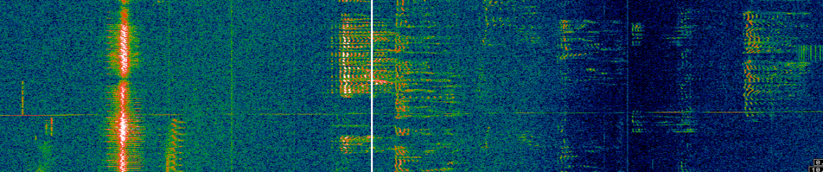
To get a good signal level in the FUNCube Dongle Pro+, the LNA has to be turned off, or otherwise the signal will be way too high. The mixer gain is left on and the baseband gain is set to 0dB. With these settings, it takes a “First FFT amplitude” of 100 in Linrad to obtain good signal levels, with the noise floor at about 30dB. The screen in Linrad has been set up as in the following picture, which shows a segment of the 20m amateur band.
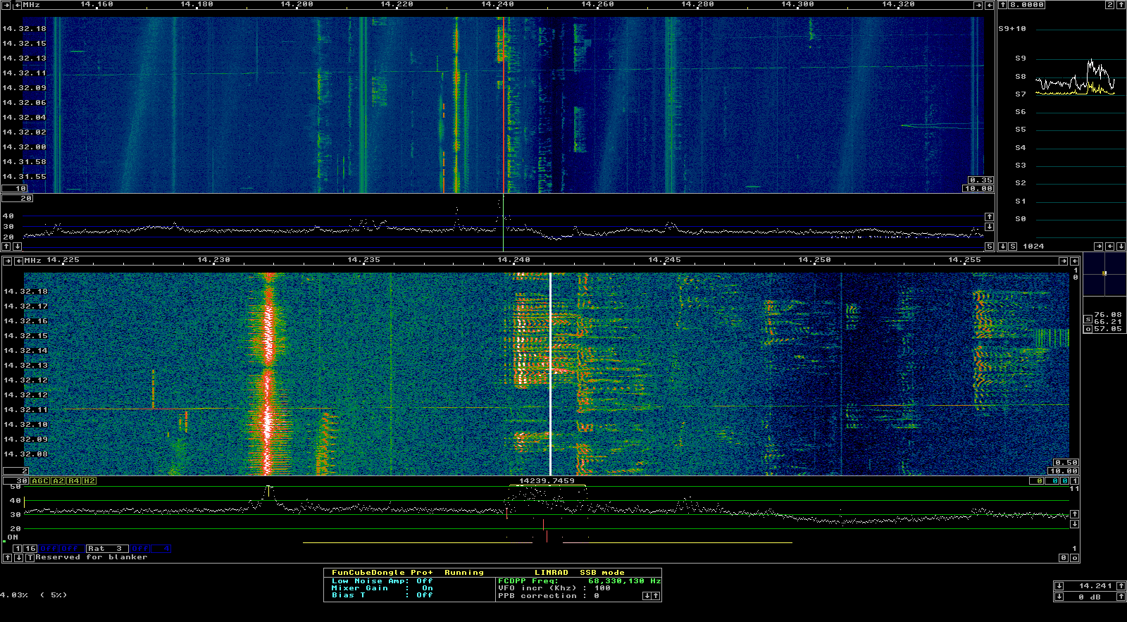
The main waterfall gives the full 192kHz bandwidth. The averaging rate gives around 25 seconds of history. This is good enough to give a summary of band activity while still being responsive when tuning around. The “baseband” waterfall is set to give about 40kHz with a history of 10 seconds. This shows many fine details of the SSB signals, such as the presence of any splatter.
The FUNCube Dongle has quite a large DC spike. Of course, it has to be placed somewhere, so I have decided to place right in the middle of the passband of the FT-817ND, so that the station tuned on the FT-817ND falls on top of it. It turns out that the exact frequency is 68.330130MHz. This makes it easy to see at a glance which signal is tuned in the FT-817ND, and is very helpful when tuning around. The downside is that you can’t use Linrad to listen to that particular frequency, which is not a big deal, because I’m already using the FT-817ND for that, and you can’t use the S-meter in Linrad for that particular frequency. This would have been nice, because the S-meter on the FT-817ND is quite far from being linear, so perhaps the S-meter in Linrad could have been used to give better signal reports.
One thing that it’s worth to notice is the notch that it’s present 10kHz above the centre frequency. It is 10dB deep and it’s a “feature” of the IF tap at the FT-817ND. Perhaps this can be compensated by calibrating Linrad, but I haven’t tried to do it yet.
To set up the frequency readout in Linrad, the frequency converter feature can be used. This is normally used for a transverter, but if it is set as an upconverter with LO of 68.330130MHz above the IF, the frequency tuned in the FT-817ND will be shown at 0MHz in Linrad and the sideband direction will be correct (recall that the IF of the FT-817ND is sideband inverting). However, I really wanted to have Linrad display the proper frequencies and that these change on the fly as I tune around. I exchanged a few emails with Leif Åsbrink to see how I could implement this in Linrad. I have ended up writing a small piece of code that has already being included in the SVN repository by Leif. See the file users_panadapter.c in the Linrad source code for detailed instructions (the SVN repository can be checked out with svn checkout https://svn.code.sf.net/p/linrad/code/trunk linrad).
This piece of code works in a simple way. It gets the dial frequency of the radio using Hamlib every 100ms (this gives a nice response while tuning around). Then, it updates the LO frequency of the frequency converter in Linrad internals accordingly. The frequency converter still needs to be set up in Linrad. Detailed instructions to do so are provided in the source code. This allows one to use different conventional radios with different IF frequencies.
In the end, I’m pretty satisfied with my set up for the panadapter. As an extra bonus, recall that the PAT is unpowered during transmit. It happens that the signal that leaks through at the IF has just the right level to allow me to monitor my transmission without changing anything. This is quite handy, especially when using digital modes.
Quick follow-up: After some experimentation I have found that I prefer not to have the DC spike right in the middle of the passband, so I can use the S-meter in Linrad and have a good view of the signal I’m tuned to in the FT-817ND. I have placed the DC spike 10kHz to the left of the centre, and this seems to work well for me.