LTE uplink: PUSCH

This post belongs to my series about LTE. In the LTE uplink, the PUSCH (physical uplink shared channel) is the channel used to trasmit data from the UEs (phones) to the eNB (base station). It plays a role analogous to the PDSCH (physical downlink shared channel), which is used to transmit data in the downlink. In this post I will decode the PUSCH in a recording that I made of my phone uplink a couple years ago.

The PUSCH uses the same kind of techniques as the PDSCH for transport block coding, so all the Turbo code implementation and related algorithms from my post about the PDSCH will be re-used here. However, there is an important difference between the PDSCH and the PUSCH that makes decoding the PUSCH much harder. The LTE downlink is, in a certain sense, a self-descriptive signal. The UEs don’t know in advance the configuration that will be used to transmit each transport block in the PDSCH, because the eNB decides it on the fly. Therefore, the eNB announces PDSCH transmissions in the PDCCH (physical downlink control channel).

When I decoded the PDCCH and PDSCH, the only slightly clever thing that I had to do was to find the RNTIs (radio network temporary indicators). These are 16-bit numbers that are used to address each PDSCH transmission. There are some of them which are statically allocated to some broadcast purpose (SI-RNTI, P-RNTI, RA-RNTI), and the C-RNTIs, which are individually assigned to each UE. The CRC-16 of the PDCCH DCIs is XORed with the RNTI to which the transmission is addressed. At any time, a UE knows the set of RNTIs that it is monitoring, so it calculates the CRC-16 of the received DCI, computes its XOR with each of its assigned RNTIs, and compares the result with the CRC-16 in the DCI. If there is a match, the DCI is accepted. This is a way of filtering out messages without spending additional bits to put the RNTI in a field in the DCI.

When we are monitoring an LTE downlink, we don’t know which RNTIs are being used. With some cleverness, if the SNR is good enough, we can detect and select each PDCCH transmission by hand (it is necessary to guess the REGs that it occupies and the DCI length) and then, assuming that we have decoded the DCI with no bit errors, obtain the RNTI as the XOR of the calculated CRC and the received CRC. This is what I did in the post about the PDCCH. If we were monitoring the LTE downlink for a longer time, this trick wouldn’t even be necessary. The C-RNTIs assigned to the UEs are communicated to them in a RAR transmitted with the RA-RNTI, as a response to their PRACH (see the post where I analyze this in Wireshark). So a downlink monitor application can simply watch the SI-RNTI, P-RNTI and RA-RNTI, and add any C-RNTIs to a list of known connected UEs when it sees a RAR. The C-RNTIs can be removed from this list after a period of inactivity, because the UE would have been sent to the idle state by the network. This idea really shows that it is possible to decode everything in the LTE downlink without doing clever blind decoding tricks.

In contrast, the LTE uplink is not self-descriptive. The eNB defines the configuration of each PUSCH transmission when it sends the uplink grant to the UE. So the UE doesn’t need to communicate this configuration again to the eNB when it transmits in the PUSCH. The information that describes the PUSCH transmissions is effectively in the PDCCH in the downlink, and in this case I don’t have a recording of the downlink that matches my uplink recording. This makes decoding the PUSCH much more difficult, but nevertheless not impossible. With some clever ideas and blind decoding tricks we can usually find all the information we’re missing. In the rest of this post, I describe how to do this in detail. It will be long and quite technical.

Decoding the LTE-M SIB-BR

LTE-M is a family of several configurations supported by LTE for machine-to-machine and IoT communications. In this post I will talk specifically about BL/CE (bandwidth reduced low complexity / coverage enhancement), which is also known as LTE Cat M1. The main difference between a BL/CE UE and a regular LTE UE is that a BL/CE UE only supports a bandwidth of 1.4 MHz (in practice, 6 resource blocks, or 1.08 MHz) and can be half-duplex. These limitations reduce the cost, size and power of the UE, but require additional techniques to handle them.

If we think about the downlink, there are several signals that occupy the whole cell bandwidth, which is usually larger than 1.4 MHz. These are the PDCCH (physical downlink shared channel), the PCFICH (physical control format indicator channel) and the PHICH (physical hybrid-ARQ indicator channel). A BL/CE UE cannot receive any of these, so alternative signals must be used to provide similar functionality. Additionally, a BL/CE UE needs guard intervals in the time domain to support retuning of the 1.4 MHz slice in which the UE operates, and transmit/receive switching for half-duplex UEs. Another distinguishing feature of BL/CE is that messages are often repeated multiple times in order to support working with worse signal conditions than what is possible with a regular UE.

In LTE, the PSS and SSS (primary synchronization signal and secondary synchronization signal), as well as the PBCH (physical broadcast channel) occupy the central 6 resource blocks, so a BL/CE UE can synchronize to the cell and decode the MIB transmitted in the PBCH. The next step that a regular UE would perform is to monitor the PDCCH, first to find a SIB1 transmission (which is transmitted in the PDSCH), and then the rest of the SIBs (whose transmission schedule is listed in the SIB1). A BL/CE UE cannot do this, because it cannot receive the PDCCH and because the SIB PDSCH transmissions might be wider than 6 resource blocks. Therefore, in a cell that supports BL/CE UEs there are also SIB-BRs (BR stands for bandwidth reduced), which BL/CE UEs use instead of the regular SIBs. The SIB-BRs occupy 6 resource blocks and do not require receiving the PDCCH to be decoded. In this post I will use my recording of an LTE eNB to show how to decode the SIB-BRs, and other important aspects of BL/CE UEs.

Published
Categorised as Software Tagged

Analysing the srsRAN LTE MAC layer with Wireshark

In my previous posts I have been decoding LTE PDSCH (physical downlink shared channel) transmissions from an IQ recording of an eNB and looking at the MAC PDUs with Wireshark. The analysis I have done of the upper layer protocols is somewhat limited because I have decoded only 500 ms of traffic and because I don’t have the encryption keys, and also because I’m just beginning to learn how the LTE upper layers work. When doing this analysis I thought that it would be good to have a more complete example that I could use as a reference. A Google search for examples of PCAP files containing LTE MAC PDUs yields very little, so I thought I would make my own example with srsRAN. In this post I show how to set up an srsRAN LTE eNB and UE communicating over ZMQ on a single machine and then analyze the traffic in Wireshark.

Decoding LTE MIMO with a single antenna

In my previous post I decoded LTE PDSCH (physical downlink shared channel) transmissions from an IQ recording that I had made of an eNB recording using an USRP B205mini and a single antenna. The eNB has two antenna ports, and it uses TM4 (closed-loop spatial multiplexing) to transmit the PDSCH to each individual UE. In the post, I repeated several times that two-codeword TM4 is intended for 2×2 MIMO and relies on the receiver having at least 2 antennas in order to separate the two transmitted codewords, so I couldn’t decode these transmissions with my recording.

In this post I will show that in some cases this is not true, and these two-codeword TM4 transmissions can be decoded with just one receive antenna. I will decode some of these two-codeword transmissions from my IQ recording by using the ideas I introduce below.

LTE downlink: PDSCH

This post is a continuation of my series about LTE, where I decode a recording of the downlink signal of an eNB using Jupyter notebooks written from scratch. Here I will decode the PDSCH (physical downlink shared channel), which contains the data transmitted by the eNB to the UEs, including PDUs from the MAC layer, and some broadcast information, such as the SIB (system information block) and paging. At first I planned this post to be about decoding the SIB1. This is the first block of system information, and it is the next thing that a UE must decode after decoding the MIB (located in the PBCH) to find the configuration of the cell. The SIB1 is always transmitted periodically, and its contents and format are relatively well known a priori (as opposed to a user data transmission, which could happen at any time and contain almost anything), so it is a good example to try to decode PDSCH transmissions.

After writing and testing all the code to decode the SIB1, it was too tempting to decode everything else. Even though at first I wrote my code thinking only about the SIB1, with a few modifications I could decode all the PSDCH transmissions (except those using two-codeword spatial multiplexing, since my recording was done with a single antenna). I will still use the SIB1 as an example to show how to decode the PDSCH step by step, but I will also show the rest of the data.

The post is rather long, but we will get from IQ samples to looking at packets in Wireshark using only Python, so I think it’s worth its length.

LTE Transmission Mode 4 (closed-loop spatial multiplexing)

This is a long overdue post. In 2022, I wrote a series of posts about LTE as I studied its physical layer to understand it better. In the last post, I decoded the PDCCH (physical downlink control channel), which contains control information about each PDSCH (physical downlink shared channel) transmission. I found that, in the recording that I was using, some PDSCH transmissions used Transmission Mode 4 (TM4), which stands for closed-loop spatial multiplexing. For an eNB with two antenna ports (which is what I recorded), this transmission mode sends either one or two codewords simultaneously over the two ports by using a precoding matrix that is chosen from a list that contains a few options. The choice is done by means of channel-state information from the UE (hence the “closed-loop” in the name).

In the post I found a transmission where only one codeword was transmitted. It used the precoding matrix \([1, i]^T/\sqrt{2}\). This basically means that a 90º phase offset is applied to the two antenna ports as they simultaneously transmit the same data. I mentioned that this was the reason why I obtained bad results when I tried to equalize this PDSCH transmission using transmit diversity in another previous post, and that in a future post I would show how to equalize this transmission correctly. I have realized that I never wrote this post, so now it is as good a time as any.

LTE downlink: PBCH and PDCCH

This post is a continuation of my series about LTE signal analysis. In the previous post I showed how to decode the PHICH. Now we will decode two other downlink channels, the PBCH (physical broadcast channel) and the PDDCH (physical downlink control channel).

The PBCH is used to transmit the MIB (master information block). This is a small data packet that all the UEs must decode after detecting a cell using the synchronization signals. The MIB contains essential information for the usage of the cell, such as the cell bandwidth and PHICH configuration. The PDDCH contains control information, such as uplink grants and the scheduling of the PDSCH (physical downlink shared channel).

The PBCH and PDDCH use the same kind of channel coding: a tail-biting k=7, r=1/3 convolutional code with a circular buffer for rate matching that performs puncturing and repetition coding as needed to obtain the required codeword size. The remaining aspects of the PBCH and PDDCH are quite different, so they will be treated separately.

As usual, we will be using a short IQ recording from my local cell site. The link to the recording is given at the end of the post.

LTE downlink: PHICH

This is a continuation of my series of posts about LTE. In the previous post we looked at the downlink cell-specific reference signals (CRS), transmit diversity equalization, and the demodulation of the PBCH (physical broadcast channel), PCFICH (physical control format indicator channel) and PDSCH (physical downlink shared channel). In this post we will look at the PHICH (physical hybrid ARQ indicator channel). As usual, I will be analysing the recording of a base station that I did in the first post about the LTE downlink.

The PHICH is used to send hybrid-ARQ ACK/NACKs to the UEs. Each PHICH transmission carries a single bit, either ACK (encoded by the bit 1) or NACK (encoded by the bit 0). Repetition encoding is used to increase the chances of correct decoding, and an orthogonal overlay code allows transmitting information for several UEs using the same resource elements.

The PHICH is transmitted in the control region of the subframe, which is formed by the first 1, 2, or 3 symbols of the subframe (according to the CFI value). As other control channels, the PHICH uses REGs. Recall that a REG is a set of 4 resource elements which are not used for the transmission of the CRS and which are adjacent in frequency if we ignore the resource elements used for the CRS. For instance, when 2 or 4 antenna ports are used for the CRS, in the first symbol of the subframe two resource elements in every block of 6 are used for the CRS. The other 4 resource elements form a REG. Therefore, there are 2 REGs per resource block. In symbols 2 and 3 there may not be resource elements allocated to the CRS, so there are 3 REGs per resource block in that case.

A PHICH transmission uses 3 REGs which are equally spaced over the bandwidth of the cell, in order to give frequency diversity. This is similar to the PCFICH, which uses 4 equally spaced REGs in the first symbol of the subframe. Depending on the configuration of a parameter called PHICH duration, the PHICH can either use the first symbol in each subframe (normal PHICH duration), or the first 2 or 3 symbols in each subframe (extended PHICH duration). Here we will only look at the normal PHICH duration, which is what is used in the recording. In the normal duration, the 3 REGs are transmitted simultaneously in the first symbol of the subframe. In the extended duration the 3 REGs are distributed over the first 2 or 3 symbols of the subframe.

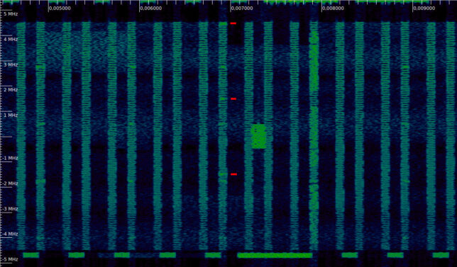
In the waterfall below we can see a PHICH transmission. In the first symbol of each subframe we can see the 4 REGs used by the PCFICH (the lower frequency REG, at around -4 MHz is barely visible). In the subframe near the centre of the image (which incidentally contains the synchronization signals), in addition to these 4 REGs, there are 3 more REGs in use, which I have marked with red ticks. These form a PHICH transmission.

Waterfall of an LTE downlink signal, showing PHICH transmissions

LTE downlink: reference signals and transmit diversity

In this post I continue with the analysis of an LTE downlink recording, which I started by looking at the primary and secondary synchronization signals. This recording is a one second excerpt of a 10 MHz cell in the B20 band that I recorded close to the base station, with a line-of-sight channel.

Now we will handle the reference signals to perform channel estimation. This will be used to equalize the received data transmissions. We will also handle the transmit diversity used by the base station, and show how to locate and demodulate some of the physical channels. All the calculations and plots are done in a Jupyter notebook.

The cell-specific reference signals (CRS) are transmitted in every subframe across all the cell bandwidth. They can be transmitted on either one, two or four antenna ports. In LTE, the concept of an antenna port does not necessarily correspond to a physical antenna. Signals are said to use the same antenna port if they have the same propagation channel to the user. Therefore, different beamforming combinations of the same physical antennas constitute different antenna ports.

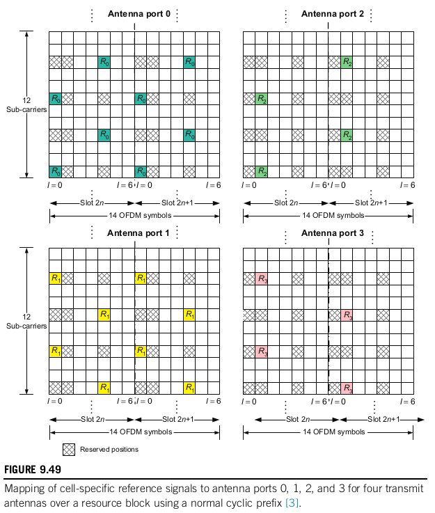
The figure below shows the resource elements that are used for the reference signals in each of the ports. The resource elements allocated to reference signals for the antenna ports that are active are only used for this purpose, and only one of the ports transmits the reference signal in each of these resource elements. For instance, say that the cell uses two antenna ports. Then the elements marked as \(R_0\) and \(R_1\) below will only be used for the CRS, while the elements marked as \(R_2\) and \(R_3\) are free and can be used for other purposes.

Allocation of resource elements to CRS (taken from the LTE-Advanced book by Sassan Ahmadi)

To the pattern shown above, a frequency offset that consists of the PCI (physical cell ID) modulo 6 subcarriers is applied. This is done so that the reference signals of cells having different PCIs use different subcarriers, so as to prevent interference (especially those cells in the same group, since their PCI modulo 3 is different).

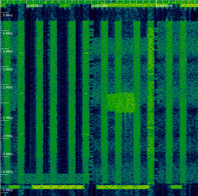
In the waterfall of our recording, we can clearly see the CRS transmissions. They last one symbol and occupy the whole bandwidth of the cell. We can also see the PSS, SSS and PBCH, as we remarked in the previous post. These indicate us where the subframes start. Thus, we can see that the first and fifth symbol of each slot are used for transmission of the CRS. This means that the cell does not use four antenna ports, since their corresponding CRS would be transmitted on the second symbol of each slot.

Waterfall of the downlink recording, showing CRS, PSS, SSS and PBCH

LTE downlink: synchronization signals

I have been posting about analysing LTE signals, with a focus on the structure of the pilot signals. I my two previous posts on this topic, I looked at the uplink using an IQ recording of my phone. Now I turn my attention to the downlink. I have done a short recording of the B20 band carrier of my local base station and I will be analysing it in this and future posts.

In this post, we will look at the primary synchronization signal (PSS) and secondary synchronization signal (SSS). These are the first signals in the downlink that a UE (phone) will attempt to detect and measure to estimate the carrier frequency offset, symbol time offset, start of the radio frames, cell identity, etc.

In an FDD system such as the one we are looking at here, the PSS is transmitted in the last symbol of slots 0 and 10 in each radio frame (Recall that LTE FDD signals are organized in 0.5 ms slots each containing 7 OFDM symbols. A radio frame lasts 10 ms and contains 20 slots). The SSS is transmitted on the symbol before the PSS.

The figure below shows the waterfall of the first 20 ms of the recording. I have marked the locations of the PSS and SSS with a red tick. These signals only occupy the 6 central resource blocks (1.08 MHz), so that they are compatible with all the possible cell bandwidths (LTE supports cell bandwidths of 1.4, 3, 5, 10, 15 and 20 MHz) and can be received by a UE which doesn’t know the cell bandwidth yet. In this case, we are looking at a 10 MHz cell, and we can see the neighbouring 10 MHz cells in the top and bottom of the waterfall.

Waterfall of LTE downlink carrier. Synchronization signals are marked with a red line.

We can see that every other PSS and SSS transmission there is another 1.08 MHz transmission following it. This corresponds to the PBCH (physical broadcast channel), which is transmitted on the first 4 symbols of slot 1 in each radio frame. The keen reader will have noticed that the PBCH is slightly wider than the PSS and SSS. This is because the PSS and SSS only use the central 62 out of 72 subcarriers in the 6 resource blocks they occupy, leaving 5 subcarriers at each edge as a guardband. This helps UEs having a large carrier frequency offset to detect these signals. On the other hand, the PBCH occupies all the 72 subcarriers.