This is a follow-up to my previous post, where I explained the modulation and coding of Tianwen-1’s telemetry. In this post I will explain the framing structures and the data contained in the telemetry (though we only understand a few of the telemetry channels). Most of what I’m going to explain here was found first by r00t.cz and is already presented in his Tianwen-1 page. In this post I’ll try to give a bit more detail (especially for those not so familiar with the CCSDS protocols) and some Python code for those interested in digging into the data.
The data used is in this post was collected by AMSAT-DL using the Bochum observatory 20m dish and the GNU Radio decoder between 2020-07-30 22:22 and 2020-07-31 06:34 UTC. The Jupyter notebook used to process this data can be found here and the data can be downloaded using git-annex as indicated in the README.
AOS frames
Tianwen-1 telemetry frames are 220 byte CCSDS AOS Space Data Link frames. The structure of the AOS Primary Header can be seen below. Tianwen-1 doesn’t use the frame header error control field.
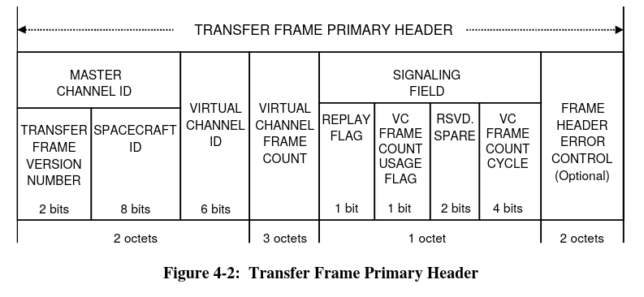
In the Bochum data there is a total of 111954 frames. Of these, around 164 frames are invalid. Since the frames use Reed-Solomon error correction, there is no CRC to check the frames, as the probability of uncorrected errors slipping through the Reed-Solomon decoder is small (but not zero). Besides the invalid frames, all the rest have a raw value of 1 in the transfer frame version number field. This indicates version 2, which corresponds to the AOS Space Data Link Protocol.
There are two spacecraft IDs in use: 82 and 245. As r00t has guessed, most likely 82 corresponds to the lander, which is currently in hibernation, and 245 corresponds to the orbiter. The data sent by spacecraft 82 changes very little. Spacecraft 82 uses only virtual channel 1, while spacecraft 245 uses virtual channels 1 and 3.
The bandwidth sharing is 25% for spacecraft 82 virtual channel 1, 50% for spacecraft 245 virtual channel 1, and 25% for spacecraft 245 virtual channel 3. The frames are usually sent in a repeating sequence with 2 spacecraft 245 virtual channel 1 frames, followed by a spacecraft 245 virtual channel 3 frame, and then a spacecraft 82 virtual channel 1 frame.
After the 6 byte AOS header we have an 8 byte transfer frame insert zone. The contents of this are not completely understood and vary between spacecraft and virtual channel, so they will be described below.
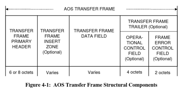
AOS frame, taken from the AOS Space Data Link Protocol blue book
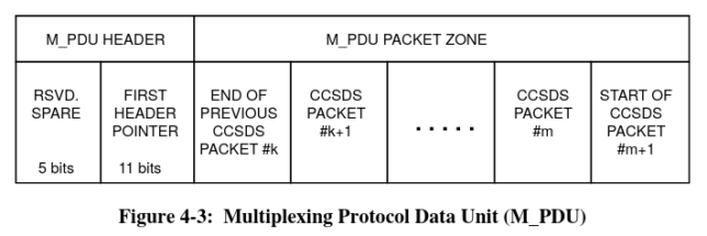
The AOS transfer frame data field uses the Multiplexing Protocol Data Unit to send several packets fragmented into the frame payload. The structure of this is shown in the figure below. The first header pointer indicates the start of packet #k+1 in the packet zone, and by reading the length of each packet in its headers, all the packets inside the packet zone can be extracted.
Space Packets
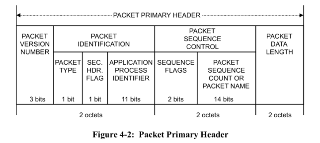
The packets carried inside the AOS frames are CCSDS Space Packets. The header of these is shown below. The packet version number has the raw value 0, which indicates version 1, the current Space Packet version. The packet type is set to 0, indicating telemetry (rather than telecommand). No secondary header is used. The application process identifier, or APID indicates the packet type.
Sometimes, padding with 0xaa bytes is used inside the M_PDU packet zone, instead of starting a new Space Packet (which might be an idle packet if there is no data to send).
Spacecraft 82 virtual channel 1
The AOS frames transmitted by spacecraft 82 virtual channel 1 have the signalling field set to zero. The 8 byte insert zone is probably divided into a 6 byte field and a 2 byte field (as it happens for spacecraft 245 virtual channel 1, where the first field contains the frame timestamp). Below some of the values of the 6 byte field are listed. I don’t know what they encode.
['0x3021af79d08',
 '0x4021bf79d08',
 '0x3021cf79d08',
 '0x3021df79d08',
 '0x3021ef79d08',
 '0x3021ff79d08',
 '0x30220f79d08',
 '0x30221f79d08',
 '0x30222f79d08',
 '0x40223f79d08']
The 2 byte field is always 0x4011. This field is static and has a different value for each of the spacecraft and virtual channel combinations.
After extracting the Space Packets, we get the following number of packets for each of the APIDs in use
1: 27944
2: 27944
5: 2889
129: 25049
130: 25054
131: 5781
136: 22162
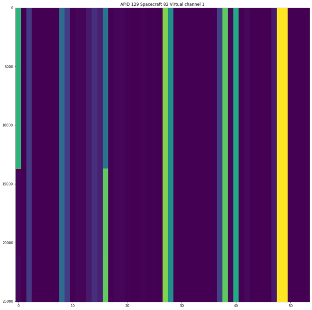
The contents of most of the APIDs is static and doesn’t change. Below we see one of the few APIDs with small changes. Images for the data in each of the APIDs can be found in the Jupyter notebook.
Spacecraft 245 virtual channel 3
Spacecraft 245 virtual channel 3 transmits only padding. Most of the bytes in these AOS frames are always 0xaa. The exception is the last two bytes of the insert zone, which contain 0x8aaa, and the first five bytes of the AOS header.
The signalling field byte of the AOS header also contains 0xaa, so my impression is that it has been overwritten with this padding value rather than containing valid data. In fact, the value of 0xaa makes the reserved field contain non-zero bits (which is not allowed), and also makes the VC frame count usage flag zero but the VC frame count cycle non-zero (which is not allowed either).
Spacecraft 245 virtual channel 1
Spacecraft 245 virtual channel 1 is the most interesting, since it contains all the changing data. As in the case of spacecraft 82, the signalling field of the AOS frames in this channel is set to zero.
The 8 byte insert zone is clearly divided into two fields. The first field is 6 bytes long and contains the frame timestamp. As described in this post, it is a 48 bit big-endian integer in 100us units using the epoch 2015-31-12 16:00 UTC. The second field is 2 bytes long and always contains the value 0x4aaa (note the similarity with the value transmitted in virtual channel 3).
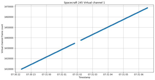
The timestamp and virtual channel frame count information is shown in the figure below. There is a period of signal outage around 02:00 UTC. Most likely this is due to a problem with the decoder at Bochum rather than some change at the spacecraft (such as the spacecraft changing to the low gain antenna or to high-speed data mode), since Paul Marsh M0EYT was also monitoring and didn’t report anything unusual.
There are a large number of APIDs. Each of them is shown below together with its total packet count.
2: 27942
3: 27942
8: 3493
14: 6985
192: 3492
194: 3493
196: 3493
198: 873
200: 873
202: 3493
204: 873
206: 873
208: 873
210: 873
212: 873
214: 873
448: 1745
449: 27942
450: 3492
451: 3494
452: 3493
454: 3491
455: 13972
456: 13972
457: 1747
458: 873
460: 3490
461: 873
462: 3492
672: 1747
704: 1746
736: 1747
768: 13971
832: 13970
1024: 6987
1025: 6986
1026: 1746
1027: 873
1028: 873
1280: 27943
1281: 13972
1282: 6987
1283: 3492
1284: 3492
1285: 873
1286: 873
1287: 873
1288: 873
1344: 1745
1360: 873
1536: 13971
1537: 3493
APIDs 1280-1288
APIDs 1280-1288 are perhaps the most interesting, since they seem to be related to the spacecraft’s navigation and ADCS. For instance, the heliocentric state vectors that we’ve been using to track the spacecraft’s trajectory come from APID 1287.
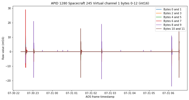
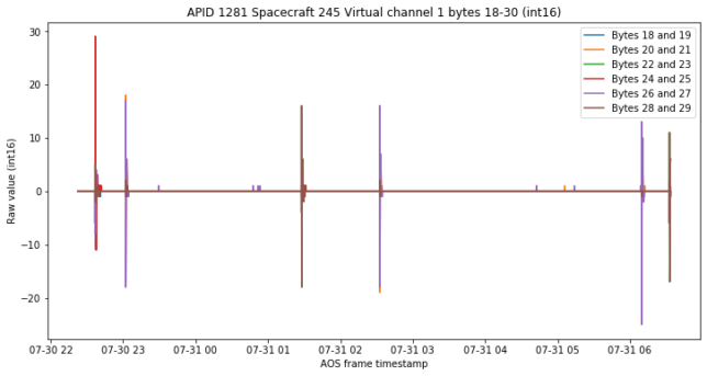
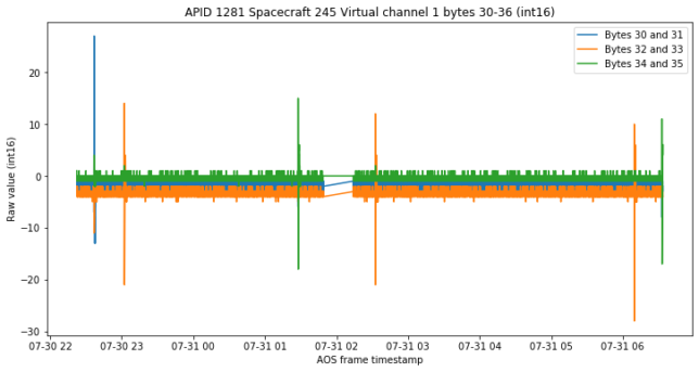
As r00t says, APIDs 1280 and 1281 contain some telemetry channels that seem to be related to the spacecraft’s dynamics. They were oscillating during the first days after launch but are now almost zero except for a few occasional “kicks” now that the spacecraft is stabilized to use its high gain antenna.
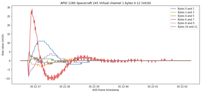
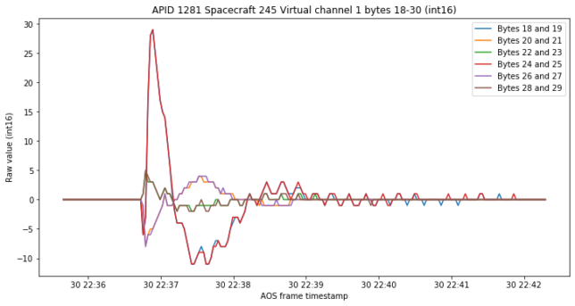
The figures below show 6 int16 channels from APID 1280 and APID 1281 that show the same occasional kicks.
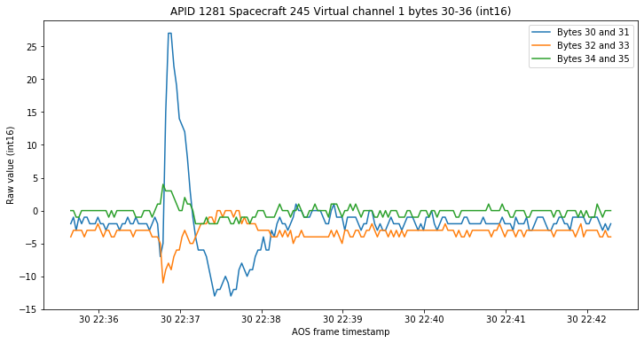
There are another three int16 channels in APID 1281 that show the kicks, but whatever sensor is used is much more noisy.
If we zoom in on the first “kick”, we see what looks like a control system’s impulse response to the kick. The red, purple and brown channels look very similar on APID 1280 and APID 1281 (except for the noise). They probably correspond to the three coordinate axes of some ADCS sensor. However, the blue, orange and green channels are different. In APID 1281 these follow the red, purple and brown channels closely. In APID 1280, however, they seem to be proportional to the integral of the red, purple and brown channels. Therefore, APID 1280 might show the state of a PI controller, with red, purple and brown being the instantaneous error, and blue, orange and green being the integrated error.
The three noisy channels from APID 1281 seem to do the same thing that the red, purple and brown channels above. However, there is also some sensor bias.
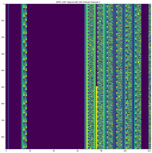
The figure below shows the frames from APID 1287, which contains the orbit state vector data. We can see the timestamps on the left (note that most APIDs do not contain timestamps inside the Space Packets), the 6 state vectors as float64s, and two bytes which I don’t know what they are. The timestamps use the same format as in the AOS frame insert zone.
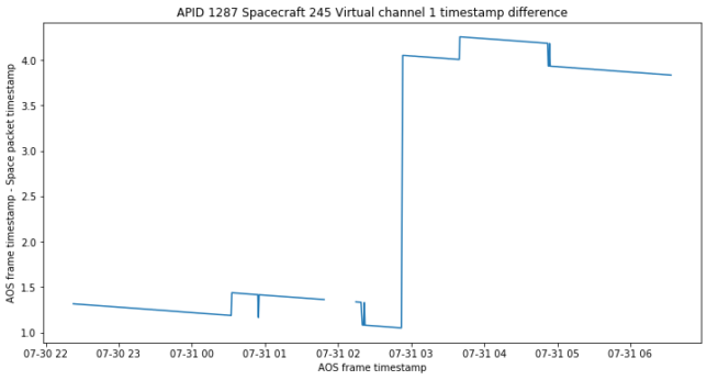
Since the packets on APID 1287 contain timestamps associated to the data, it is interesting to compare these with the timestamp of the AOS frames carrying each packet. The timestamp difference is shown below. We see a slow decreasing trend that is caused by the fact that state vector data is not generated at exactly the same rate that frames are sent. A frame is supposed to take 0.25 seconds to send and state vectors are generated spaced 32 seconds and sent every 128 frames in general, but these durations are not exact.
The discrete jumps of 0.5 seconds corresponds to the packet getting two AOS frames ahead or behind. Note that to change its relative position, the space packet must jump over two frames, which are allocated to spacecraft 245 virtual channel 3 and spacecraft 82 virtual channel 1.
We see a large increase in delay shortly before 03:00 UTC. Below we will see that this coincides with some telecommands received by the spacecraft. Maybe these telecommands generate immediate responses in the telemetry and so the APID 1287 get queued and lag behind.
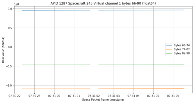
Below we show the data corresponding to the first three float64 channels, which give the position of the spacecraft as heliocentric ICRF coordinates in km.
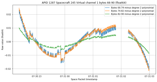
In order to see fine detail, we fit and remove a quadratic polynomial from the data. We see a jump of approximately one km shortly after 03:00 UTC.
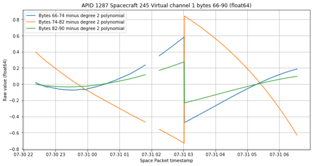
The jump prevents a good polynomial fit, so we select only the portion of data preceding the jump and perform the fit again. We see many jumps of a few m. I don’t think these are caused by numerical precision of the float64, since for 1e8 km the precision would be on the order of 1e-8 km. They might be caused by the precision of the timestamp. The spacecraft moves at approximately 30km/s in heliocentric coordinates, and the timestamp has a resolution of 100us, so the spacecraft moves approximately 300m per timestamp LSB. Thus, unless the timestamps are exact, we will see jumps of this order of magnitude in the position.
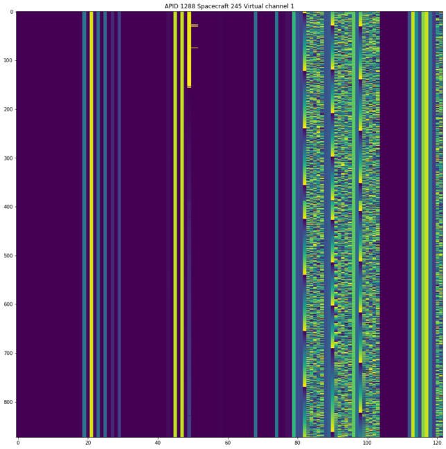
APID 1288 also contains three float64 channels, which can be clearly seen below.
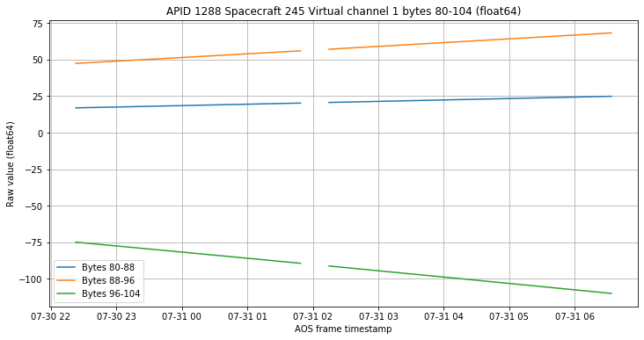
The data from these three channels is shown below. Interestingly, this doesn’t look very much like the plot on r00t’s page (look for APID 0x508), which was done with data from 2020-07-26. In there, r00t had values close to zero. If we imagine what has happened in between these days, we might think that the values have started to diverge away from zero, as the end of r00t’s plot might suggest. r00t says that these values were zero before the high gain antenna was active, and relates them to the antenna pointing, but I’m not so sure that this has to do with the antenna.
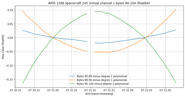
Since there is a clear linear trend in these values, we can fit and remove a degree one polynomial to see the fine detail better. By doing so, we already see a small jump in the data some time before 03:00 UTC, coinciding with the telecommand reception.
If we fit a degree 2 polynomial instead, in order to remove the quadratic trend, what remains looks like a sensor noise process of some sort.
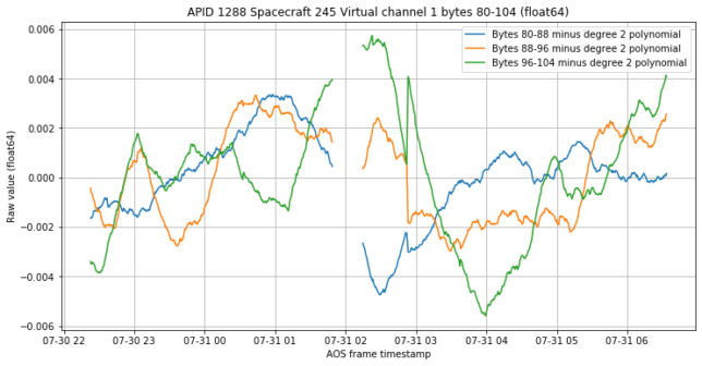
I don’t have a clear idea of what we’re looking at here. But these channels seem quite interesting, so it might be good to study them further.
APIDs 2, 3 and 454
r00t says that APIDs 2 and 3 correspond to redundant command decoders and the first byte corresponds to the number of decoded frames. This seems to be the case. Looking at APID 2, we see that something happens in the middle of the data, and some of the channels change their value.
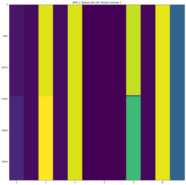
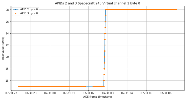
The values in APID 2 and APID 3 coincide. Here we show the first byte of both, and see that it increases in steps of one shortly before 03:00 UTC. I don’t have the spectrum of the signal to see if this corresponds to 13 telecommands sent at that time, but probably it does. Interestingly, it seems that the small jump in the data from APID 1288 coincides with these telecommands.
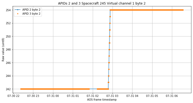
It seems that byte 2 also counts telecommands, but probably only those of a certain type (or those that decoded correctly). Note that it only increases by 12 units rather than 13.
Byte 4 also contains some information about the telecommands.
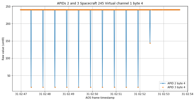
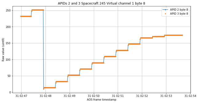
Finally, byte 8 also increases whenever a command is received, but it increases by a different amount with the last command (which seems somehow special also according to byte 4), and then it increases again.
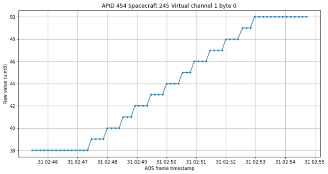
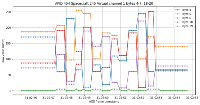
APID 454 contains a few bytes that also seem to respond to telecommand reception. One of them increases by one every time a command is received, while the others are harder to interpret.
APIDs 462 and 1536
APIDs 462 and 1536 contain a few int16 channels that are interesting to see, except that I have no clue what we’re looking at. These are shown below. In one of the channels there are spikes that coincide with the “kicks” seen in APIDs 1280 and 1281.
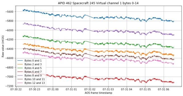
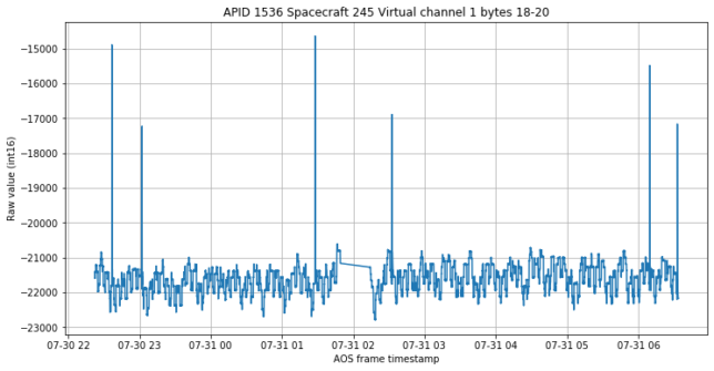
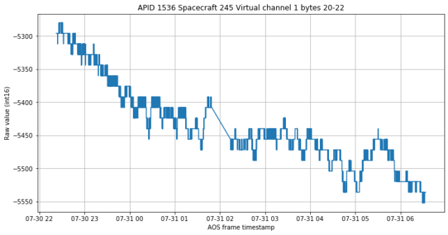
APIDs 462 and 1536 probably contain temperature sensor data. The circuit used to measure the temperature sensor and the type of sensor dictate how those integers would be converted into real temperature units. As such these should probably be interpreted as UINT16 instead of INT16.