ArgoMoon is one of the ten cubesats that were launched in the Artemis I mission. It was built by the Italian private company Argotec, and its main mission was to image the ICPS after the separation of Orion, and while the other cubesats were deployed.
In 2022-11-16, about seven hours after launch, I used two antennas from the Allen Telescope Array to record telemetry from the Orion vehicle and some of the cubesats. Since then, I have been posting regularly as I analyze these recordings and publish the data to Zenodo. In this post I will look at two recordings of the X-band telemetry signal of ArgoMoon at 8475 MHz. In the two recordings, different modulation and data rate is used.
The recordings are available in the dataset Recording of Artemis I ArgoMoon with the Allen Telescope Array on 2022-11-16 in Zenodo.
Waterfalls
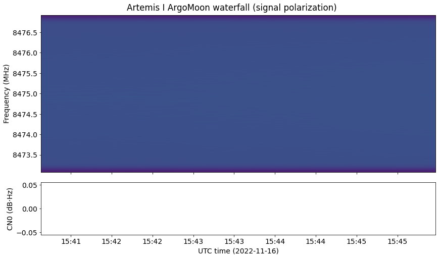
The waterfalls are computed and plotted as in the previous posts in this series. In the first recording, the signal from ArgoMoon is rather weak and has the telemetry data on subcarriers.

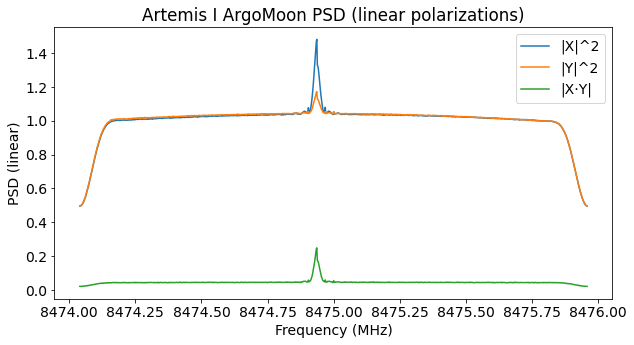
In the waterfall it is quite difficult to see anything, due to the frequency resolution and sensitivity it has. Looking at the recordings more carefully (for instance with Inspectrum) we can see what happens better. The signal is mostly linearly polarized. Most of its power is present in the Y polarization until near the end of the recording. There the signal moves to the X polarization and changes frequency, probably due to a groundstation unlock or lock. Note that the CN0 estimation isn’t giving meaningful values because the signal is too weak, which makes the estimation algorithm fail.
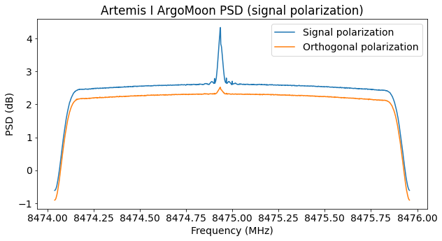
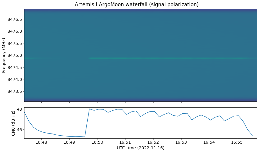
In the second recording the signal is stronger and the telemetry is now modulated in baseband with a higher symbol rate. The signal is also elliptically polarized, with most of the signal power in the X polarization.
The estimation of the elliptical polarization parameters does a reasonably good job. There is still a small amount of signal power leaking to the orthogonal polarization. Probably this is partly caused by polarization changes throughout the recording.
In the waterfall we see that there is a deep fade at the beginning of the recording, and then the signal suddenly appears again. The maximum CN0 is 48 dB·Hz.
Modulation and coding
In the first recording, PCM/PSK/PM modulation is used. The symbol rate is 2000 baud, and the subcarrier frequency is 25 kHz. The coding is CCSDS Turbo coding with r=1/2 and 8920 information bits.
Note that the subcarrier frequency is not an integer multiple of the of the symbol rate. This is recommended by CCSDS because it causes zero telemetry power to fall on the residual carrier. However, with such a large ratio between the subcarrier frequency and the symbol rate, very little telemetry power falls near the residual carrier in any case.
The figure below shows the GNU Radio flowgraph that I am using to decode the telemetry data from the first recording.
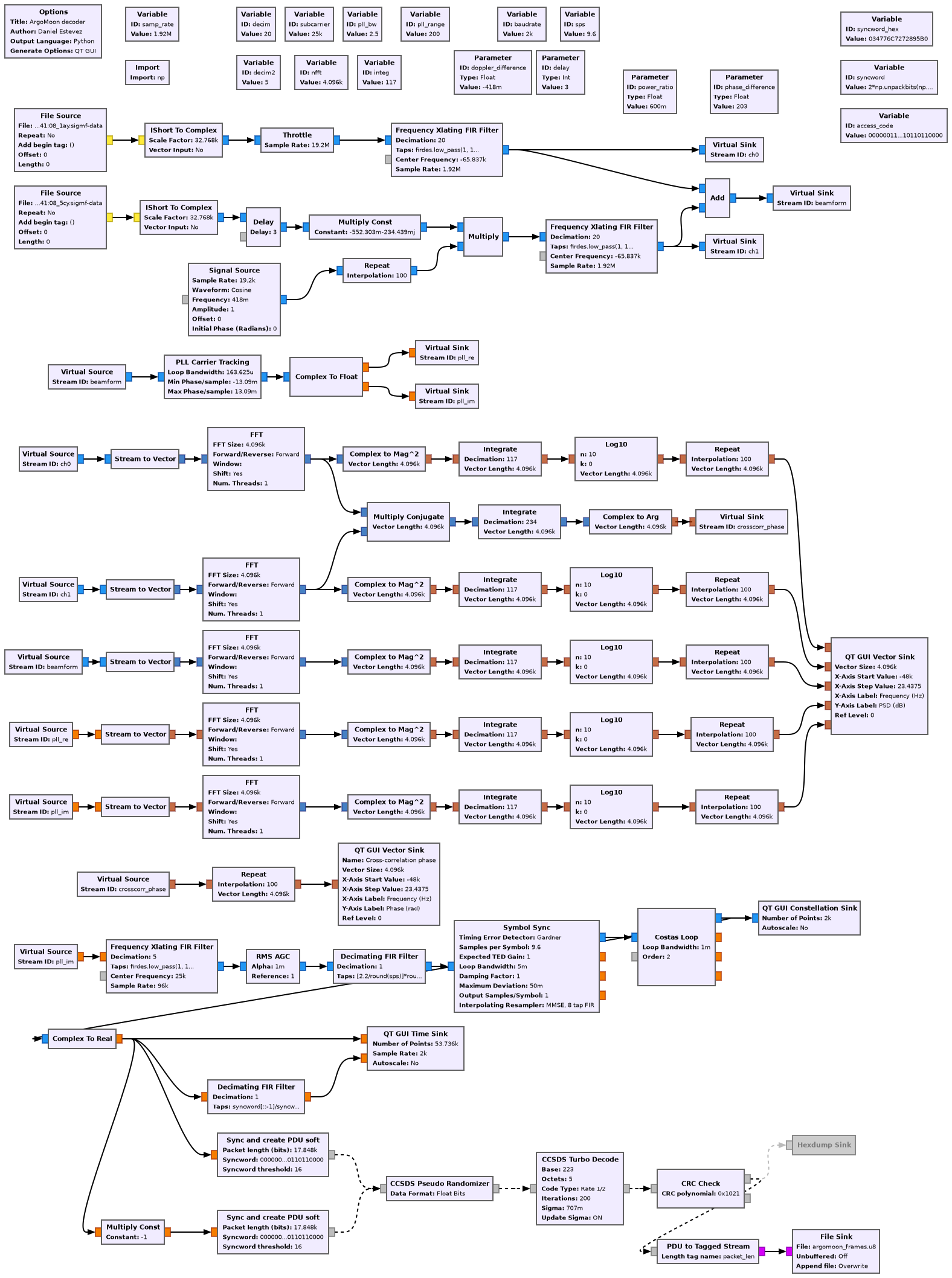
The input is the Y polarization channels from the two antennas (1a and 5c), which are beamformed to increase the SNR. The X polarization is not used because it contains very little signal power. The central part of the flowgraph computes and plots the power spectral densities of each of the two antennas and the beamformed signal, and also shows the phase of the cross-correlation between the two antennas. These plots are used to adjust the delay, amplitude, phase and frequency offsets between both antennas, in order to beamform them correctly.
The bottom part of the flowgraph is a PCM/PM/NRZ demodulator and Turbo decoder that uses some blocks from gr-dslwp.
The figure below shows the GUI of the flowgraph running with the data at the beginning of the recording. We can see that the amplitude of the two antennas has been adjusted so that they have very similar powers (note that antenna 5c has slightly more SNR than 1a). In the cross-correlation phase we can see that the phase and delay between both antennas is adjusted correctly, since the phase in the frequency range corresponding to the data sidebands is close to zero.
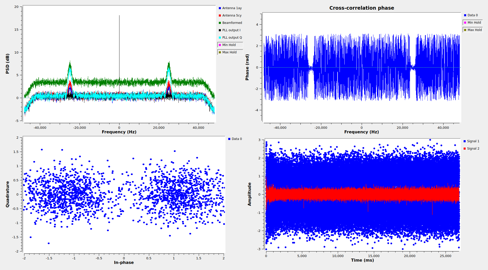
The spectrum of the PLL output shows that the PLL is locked correctly, because the residual carrier is on the I component and the sidebands are on the Q component. A PLL bandwidth of 2.5 Hz is used here.
There is a relatively clean BPSK constellation for the telemetry modulation, and the bottom right plot shows good correlations with the 64-bit ASM used by r=1/2 Turbo coded data.
In the second recording, the modulation is PCM/PM/NRZ. The symbol rate is probably a nominal of 32 kbaud. I have measured 31969 baud. The coding is also CCSDS Turbo coding with r=1/2 and 8920 information bits.
The SNR is marginal and I have not been able to decode any correct frames. For some unknown reason, the SNR in antenna 5c is much worse than in antenna 1a in this recording, so beamforming doesn’t help much.
Below is a screenshot of the flowgraph I have used to attempt to decode the signal. I am using the X polarizations from both antennas, because most of the signal power is contained there. I am beamforming antennas 1a and 5c, but antenna 5c has such a small weight due to its low SNR that it is almost as if it wasn’t present.
I haven’t been able to make clock recovery work reasonably well, so I’m also trying some kind of open loop demodulation where I have determined the symbol clock frequency by hand by looking at how the peaks of the ASM correlations drift over time and I run 6 different phases of the symbol integrations in parallel. One of them will be aligned to the symbol clock better than 1/12 symbol period.

Even though there are reasonably strong correlation peaks with the 64-bit ASM, this technique is not able to give any decoded frames. Perhaps better results could be achieved by demodulating the signal by hand more carefully.
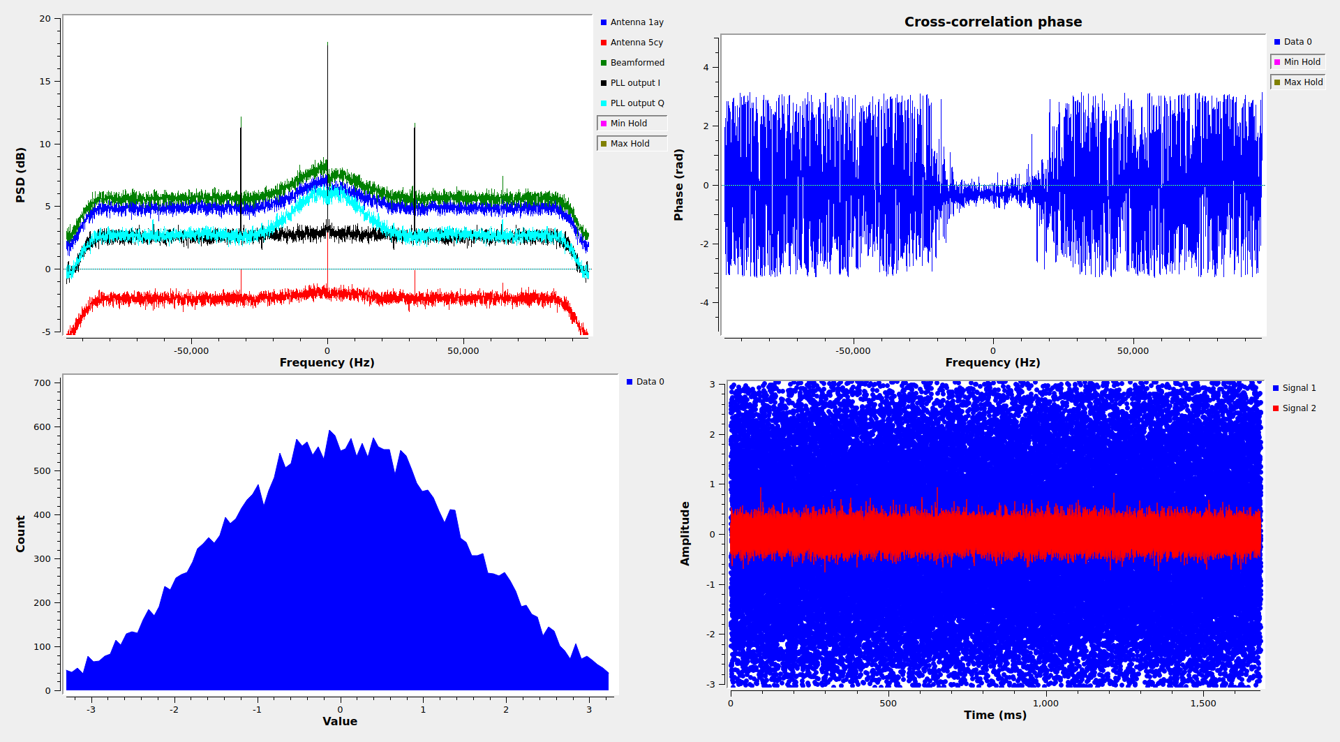
The figure below shows the GUI of the flowgraph. It is of interest that the modulation appears distorted. The power spectral density is not symmetric, and the right side appears to be notched at the residual carrier (more on this below). Note that we can also see CW carriers at an offset from the residual carrier which is equal to the symbol rate. In the output of the PLL, these appear in-phase with the residual carrier. They are due to amplitude modulation of the residual carrier caused by relatively smooth symbol transitions.
AOS Frames
The frames transmitted by ArgoMoon are CCSDS AOS Space Data Link frames. There are several similar aspects in the ArgoMoon’s frames and in LunaH-Map frames, which makes me think that both use the same radio. Janos Tolgyiesi commented that LunaH-Map uses the IRIS v2 radio, and this paper indicates that ArgoMoon also uses an IRIS radio (in fact this other paper lists seven of the Artemis I cubesats as using the IRIS). Moreover, the modulation of LunaH-Map in PCM/PM/NRZ mode also shows the same kind of artifact as ArgoMoon (see the spectrum plots in the post), so I guess that this is due to the IRIS radio.
The AOS frames use spacecraft ID 0xdf, which is assigned to AGM in the SANA registry. This ID is only assigned for the return link. The forward link uses spacecraft ID 0x3b.
Virtual channels 2 and 63 are in use. Virtual channel 2 carriers telemetry, and virtual channel 63 is only idle data (OID). The frames have a frame error control field (FECF; CRC-16) and no Operational Control Field or Transfer Frame Insert Zone. These settings are the same as in LunaH-Map.
I have been able to decode 14 frames from the first recording. Since it takes 8.956 seconds to transmit a frame, this corresponds to 35.824 seconds worth of data. According to the virtual channel frame counters, 1 frame in virtual channel 2 was lost (skipped) and another frame in virtual channel 63 was lost. After the signal fades out, there are additional frames that cannot be recorded. The signal is only strong enough to be decoded in the beginning of the recording.
The idle frames in virtual channel 63 are exactly the same as those transmitted by LunaH-Map. There is an M_PDU header that indicates that the packet zone carriers only idle data (first header pointer equal to 2046), and the packet zone is filled with 0xdc bytes.
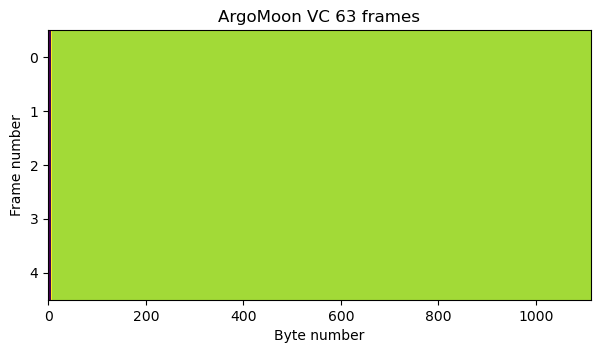
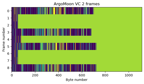
Virtual channel 2 carriers CCSDS Space Packets using M_PDU. There are two APIDs in use, APID 1, and APID 2047, which is the idle APID. The Space Packets in APID 1 have several different possible sizes, use a secondary header, and carry a valid packet sequence count. The idle packets in APID 2047 have no secondary header, and have the packet sequence count set to zero. Their data field is filled with 0xdc bytes. Idle packets are inserted as appropriate to fill in the remaining part of AOS frames. This is best seen in the raster map below that shows some virtual channel 2 frames. The idle packets stand out because all their data field appears in a green colour. Each frame carriers one or more APID 1 packets, and then an APID 2047 packet that finishes filling up the frame.
The APID 2047 idle packets are exactly the same as those used by the LunaH-Map, so I believe that they are generated and inserted by the IRIS radio whenever their is not enough user data to fill a whole AOS frame.
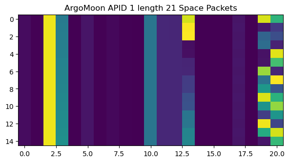
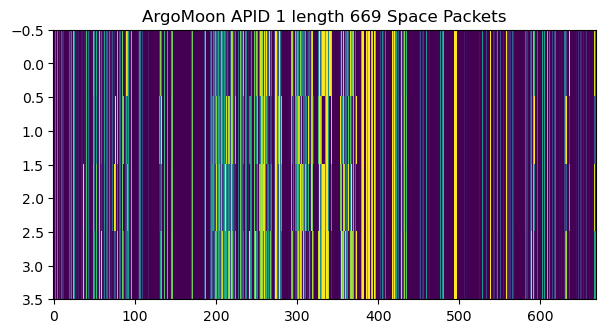
In the telemetry that I have decoded from the first recording there are APID 1 Space Packets of three different lengths. Raster maps for the packets of each of the lengths are shown here.

I have the impression that these Space Packets might use ECSS PUS, which would make sense, given that ArgoMoon is a European spacecraft. However, I haven’t been able to validate this idea completely. The first byte of the secondary header of all the packets is 0x01. This would correspond to version number and time reference status fields, as shown in the figure below. However, for the current version of PUS, the version number should be 2 rather than 0, so the values of these fields don’t make much sense.
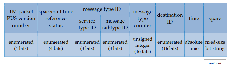
The message type ID fields make more sense. There is a one to one correspondence between the packet length and the values of these fields. Packets with length 21 have 0x0501, packets with length 27 have 0x0102, and packets with length 669 have 0x0319. These would correspond to PUS packet types TM[5,1] “Informative event report”, TM[1,2] “failed acceptance verification report”, and TM[3,25] “housekeeping parameter report”.
After the message type ID fields, we have what appears to be a 32-bit timestamp. This makes sense if the message type counter and destination ID fields are omitted.
Code and data
The GNU Radio flowgraphs and the Jupyter notebook used in this post, as well as the decoded frames, can be found in this repository. The material for the waterfalls is here. The IQ recordings are in a Zenodo dataset linked at the beginning of the post.
3 comments