The Orion Muli-Purpose Crewed Vehicle was the main spacecraft of the Artemis I mission. In a previous post I showed how to decode its OQPSK S-band telemetry signal, using a recording I made with the Allen Telescope Array. I mentioned that besides the OQPSK modulation, Orion sometimes used a different modulation with a residual carrier. This residual carrier modulation will be the topic of this post.
As we will see, the Orion residual carrier modulation is 2Mbaud PCM/PM/NRZ, which means that the telemetry is directly phase-modulated on a residual carrier. The OQPSK mode is also 2Mbaud, so it occupies roughly the same bandwidth, but gives twice the data rate (so it is sometimes referred to as 4Mbps). Richard Stephenson has mentioned that the residual carrier mode is used with ranging, and OQPSK is used without ranging.
I don’t have a very clear idea of what advantages the residual carrier mode provides over OQPSK, or in other words, what are the limitations of OQPSK regarding ranging. In principle, an OQPSK demodulator can also produce carrier phase (Doppler) observables for ranging. These will have squaring losses in comparison to a residual carrier, but with the high SNR of this signal it will hardly be a problem, plus the carrier measurement of OQPSK uses all the signal power instead of only a residual carrier (on this topic there is a good paper on residual carrier versus suppressed carrier modulations, though it doesn’t treat specifically the topic of ranging).
Besides phase/Doppler ranging, there is also the matter of two-way group delay ranging (sequential or PN ranging). For this, apparently Orion uses PN ranging. I don’t know the specific details, and I haven’t spotted the ranging signal in any of the downlink recordings I’ve seen. I have in mind the CCSDS T2B and T4B codes (plus the JPL code, which is quite similar), though I imagine that other ranging codes could be possible. If the code doesn’t have a reasonably strong ranging clock that produces CW tones at a frequency equal to the chip rate, it could be difficult to spot its presence without a knowledge of the code in use. It would be hiding below the telemetry modulation.
Regarding sequential and PN ranging, this is where a residual carrier modulation can be advantageous. In this kind of modulation, it is straightforward to multiplex a telemetry signal and a ranging signal on the same carrier, simply by adding both before phase modulation. The same is not possible with a suppressed-carrier modulation such as OQPSK, though there is a CCSDS Green Book on simultaneous transmission of GMSK telemetry and PN ranging which could be used. I think this could be the reason why Orion uses a residual carrier modulation when ranging is needed, though I’m still intrigued by not having seen ranging clock tones.
Since none of my Allen Telescope Array recordings contain the residual carrier signal, I am using the recordings done by CAMRAS with the Dwingeloo 25m radio telescope. They have done a great job tracking Orion and have published a good number of IQ recordings throughout the mission. However, the recordings are a bit tricky to work with, for two reasons. First, until November 30, the wrong polarization was used, so the signal was about 20 dB weaker than it should. Second, many of the IQ recordings use a sample rate of 2Msps, which is a bit narrow to work with a 2Mbaud PCM/PM/NRZ signal (it occupies roughly 4 MHz). Nevertheless, the recordings have served me well for my purpose of analyzing this modulation.
The best recording to study the residual carrier signal is camras-2022_11_30_19_17_04_2216.500MHz_5.0Msps_ci16_le (sigmf-meta & sigmf-data). This has very good SNR and 5 MHz bandwidth, so the signal fits fully in the passband. Looking at this recording, I found that, as mentioned above, the modulation was 2Mbaud PCM/PM/NRZ. I also found the CCSDS 64-bit ASMs for r=1/2 LDPC separated by 2112 symbols. This is the same as for the OQPSK signal, and is what we would expect for LDPC coding with r=1/2 and k=1024. However, keep reading, because there is a surprising twist.
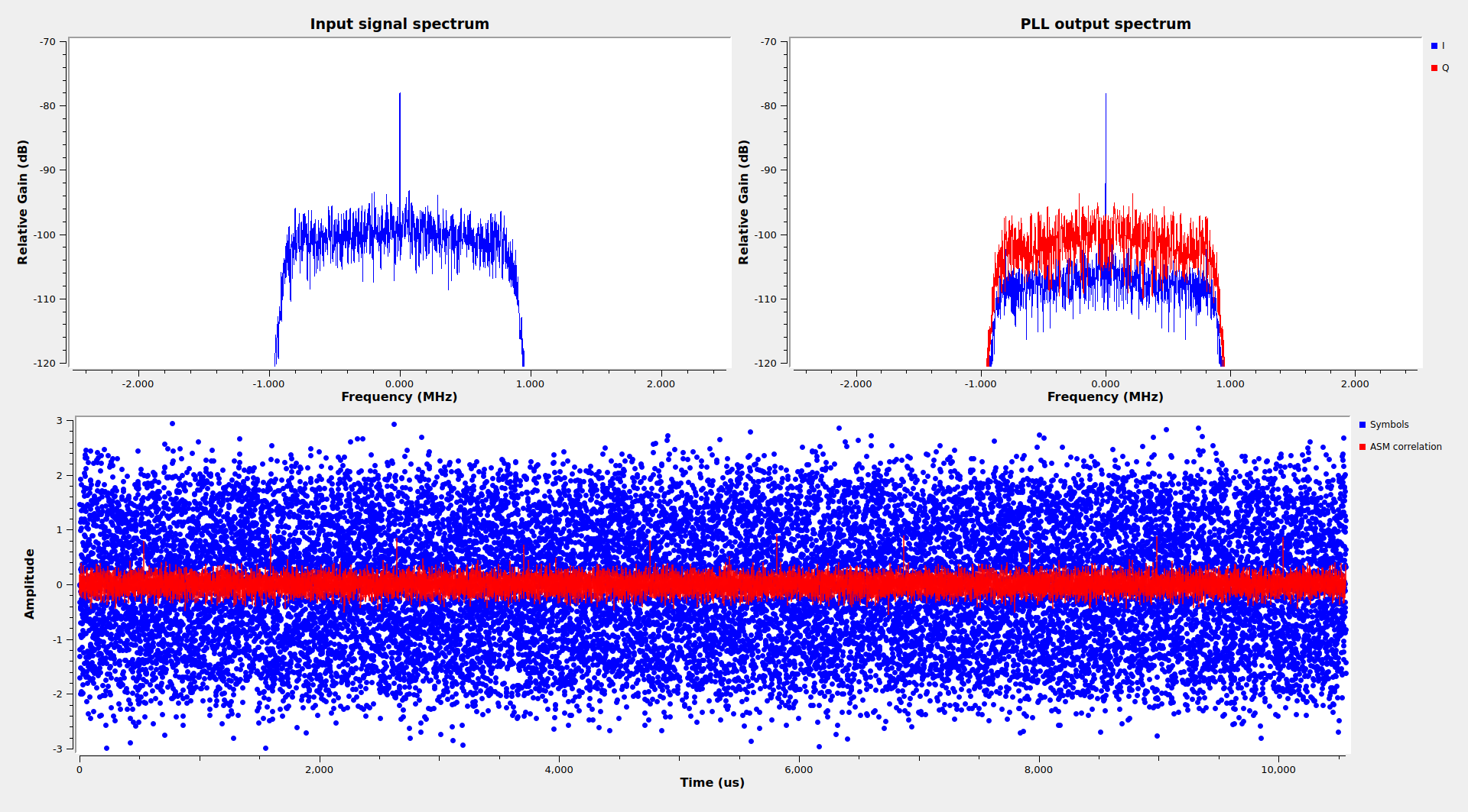
The figure below shows the GNU Radio demodulator flowgraph that I’m using with this recording. It contains a simple PCM/PM/NRZ demodulator, and then the ASMs are detected, and 2048-bit codewords are descrambled and saved to disk as soft symbols. This is the same I did with the OQPSK telemetry, in order to run LDPC decoding afterwards.
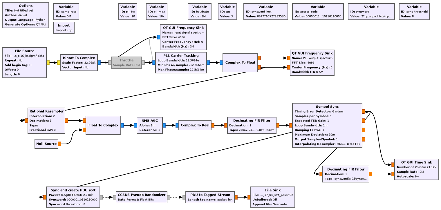
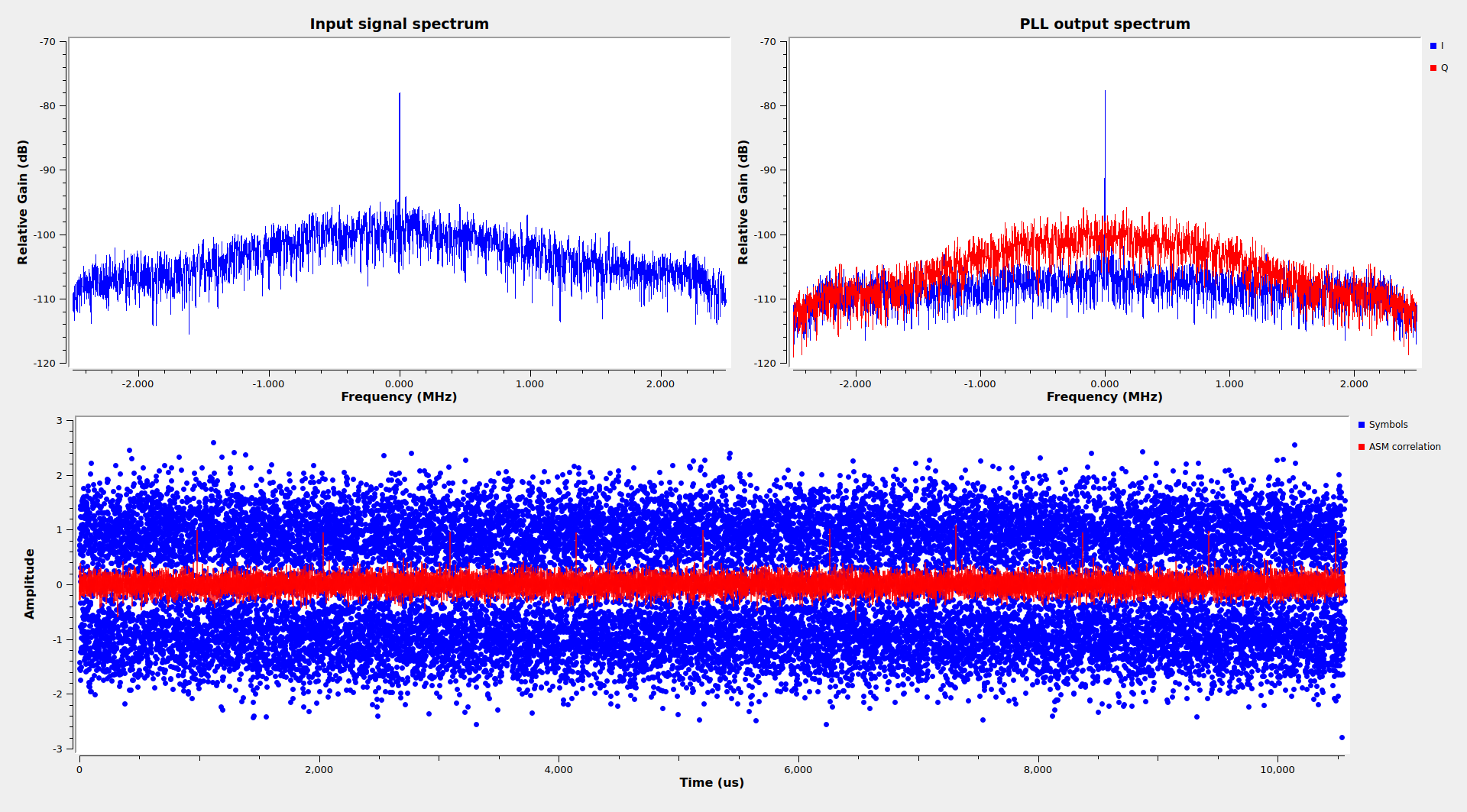
The GUI of this flowgraph shows good PLL lock, since the residual carrier is in the I component and the data modulation in the Q component. We can see very well the correlations with the ASM, and the SNR of the demodulated symbols is relatively good.
However, to my surprise, LDPC decoding using the same tool as for the OQPSK signal failed for all the frames.
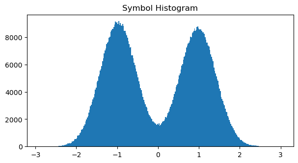
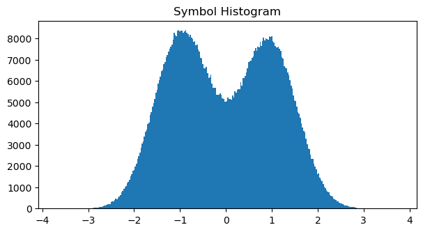
The figure below shows the histogram of the soft symbols output by the decoder. Judging from the histogram, the bit error rate is about 10%, so r=1/2 LDPC should be able to work correctly.
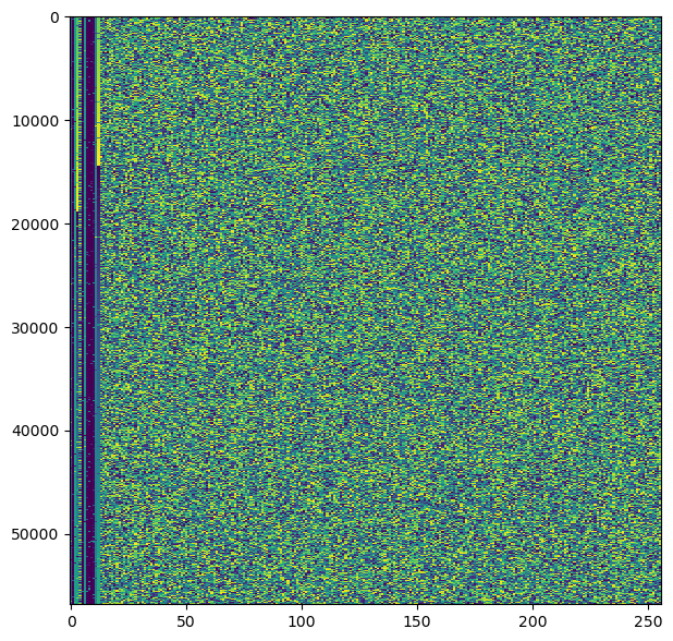
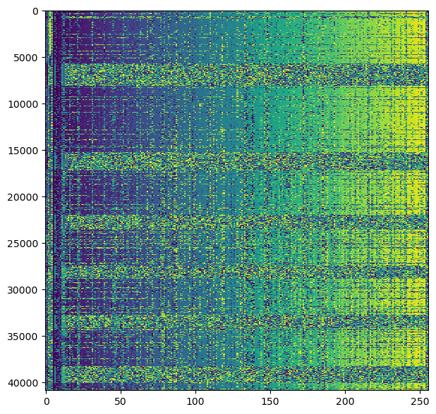
The next figure shows a raster map obtained by doing hard decision on the symbols and packing them into bytes to obtain frames of 256 bytes. The first 128 bytes should be the message (the CCSDS LDPC codes are systematic), and the remaining 128 bytes should be the LDPC parity check bits. We can see pretty much the same as in the raster maps from the OQPSK signal. The data is encrypted, but except for some occasional bit errors, the AOS Primary Headers have the correct data.
So I was left wondering why my LDPC decoder didn’t work with these frames. I even tried to gain more insight about the problem by using the following technique.
The structure of the r=1/2 LDPC parity check matrix is shown below. For k=1024, each of the submatrices is 512×512. The last column corresponds to bits which are punctured (not transmitted).
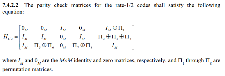
The idea is to apply the parity check matrix to the received codewords and look at how many parity equations fail. With a low BER, we would expect most equations to be correct, since they only involve a few codeword bits. However, the fact that there are punctured bits makes this more difficult.
Luckily, we can use the last row of the matrix to express the punctured bits in terms of the codeword bits, assuming that all these 512 parity equations hold. In reality, a fraction of the punctured bits obtained in this way will be wrong, due to bit errors in the codeword, but most will be correct. Then we can use these punctured bits to check whether the 1024 parity equations given by the two first rows of the matrix hold. Most of the equations should hold.
By applying this technique to the codewords I had demodulated, I found that 50% of the parity equations were wrong. This is what would happen if we start with completely random data, or if we are using a different LDPC code. What was happening? Was different LDPC code being used? The TM Synchronization and Coding Blue Book gives no room for variations if the 64-bit ASM 0x034776C7272895B0 appears every 2112 symbols. This ASM is used for r=1/2 Turbo and r=1/2, 2/3, and 4/5 LDPC. The fact that the separation is 2112 symbols means that the codewords are 2048 bits long. So the only possibility is r=1/2 LDPC with k=1024.
Having idle frames in the data would be helpful, because we know exactly how idle frames look like. Their payload is filled with a counter, so it is easy to tell apart the message from the parity check bits, which look quite random. On the other hand, the payload of telemetry frames is encrypted, so the data and the parity check bits look alike. However, this recording doesn’t contain any idle frames.
Looking at other recordings gives the clue that solves this mystery, since they contain idle frames. These other recordings are not so easy to work with, because they use 2Msps, which chops off a good part of the signal in the frequency domain, causing severe inter-symbol interference in the time domain. Nevertheless, we can still try to decode the frames, obtaining many bit errors, and then look qualitatively at the raster map.
I have adapted the flowgraph above to work with these 2Msps recordings. The clock recovery barely works, so I have determined and corrected the clock frequency by hand and used a very narrow bandwidth for the Symbol Sync block. The next figure shows the flowgraph running with okay results.
With the recording camras-2022_11_30_19_39_43_2216.500MHz_2.0Msps_ci16_le (sigmf-meta & sigmf-data), I have obtained the following symbol histogram and frame raster map.
We see that in this recording there are many idle frames, and moreover, these look different to the ones in the OQPSK recordings. In the OQPSK recording, the last 128 bytes of the idle frames look random, the same as the encrypted data. However, here we can see that the counter that fills the payload of idle frames keeps increasing until the last 2 bytes of the frame, which look random.
The logical conclusion is that in this recording, at least idle frames, are uncoded. The last 2 bytes are probably a CRC-16 (the CCSDS frame error check field). I haven’t bothered to check if this is the case, but it is possible to do it despite the large number of bit errors. We know essentially how idle frames look like (the only unknown that needs to be determined is the virtual channel frame count, which we can do by looking at several consecutive frames even if there are bit errors). Therefore, we can fix all the bit errors in a frame and compute its CRC-16. Then compare it with the last 2 bytes of the frame and see if it matches (allowing for a few bit errors when comparing).
Seeing that these frames are uncoded explains why my LDPC decoder failed. The attentive reader will have spotted that Richard Stephenson already said that uncoded frames were being used sometimes:
However, I didn’t remember that part of the tweet when doing my analysis. I guess that I didn’t pay enough attention to the full tweet and it didn’t register with me.
The use of uncoded frames here is a bit odd. First, the same ASM as for LDPC frames is maintained, whereas CCSDS recommends using the 32-bit ASM 0x1ACFFC1D for uncoded frames. Second, the uncoded frames keep the same length (2048 bits) as the LDPC frames. This would make sense from the perspective of keeping frame sizes the same in both scenarios, but this is not the case. With LPDC the AOS frames have 128 bytes due to the parity check bits, while in the uncoded setting the AOS frames have 256 bytes, of which only 254 are usable due to the CRC-16. The size of the encrypted data sent in each frame changes as a consequence.
Finally, I wonder whether the DSN has so much link budget that uncoded frames can be decoded error free. An EbN0 of 8 or 9 dB would be needed for this. If this is the case, then running uncoded would give a simple way of maximizing the data rate. But I still worry about occasionally lost frames and wonder whether using Reed-Solomon would be a better idea. Maybe the project runs some kind of ARQ, which in principle is a reasonable option, since the round-trip time is not that large.
I have also looked at another recording done in the same day, camras-2022_11_30_18_13_11_2216.500MHz_2.0Msps_ci16_le (sigmf-meta & sigmf-data). In that recording there are no idle frames either, so it is not easy to tell if it is uncoded.
I have also looked at earlier recordings to try to find if the residual carrier mode was always used with uncoded. If we read Richard’s tweet carefully, we can imagine this is not the case: the project seems to be switching between OQPSK and residual carrier and between LDPC and uncoded independently.
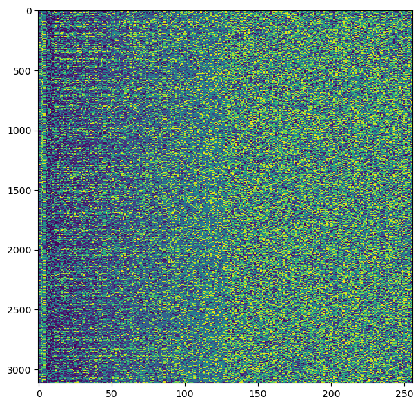
The recording camras-2022_11_17_08_56_06_2216.000MHz_10.0Msps_ci16_le (sigmf-meta & sigmf-data), recorded the day after the launch, contains the PCM/PM/NRZ signal. The SNR is quite low, however, since this was recorded with the wrong polarization. At this low SNR, the clock recovery doesn’t really work, even with very narrow loop bandwidth (I’m using this flowgraph). The symbol histogram looks awful.

Nevertheless, we can see some structure in the raster plot. It is apparent that there are many idle frames, since the left hand side of the plot looks bluish. The right half of the plot looks completely random though. This is good evidence that LDPC was being used when this recording was done.
The plots in this post have been done in this Jupyter notebook. It can be found, together with the GNU Radio flowgraphs, in this repository.
2 comments