CODAR is an HF radar used to measure surface ocean currents in coastal areas. Usually, it consists of a chirp which repeats every second. The chirp rate is usually on the order of 10kHz/s, and the signal is gated in small pulses so that the CODAR receiver can listen between pulses. The gating frequency can be on the order of 1kHz.
CODAR can be received by skywave many kilometers inland. Being a chirped signal, it is easy to extract the multipath information from the received signal. In this way, one can see the signal bouncing off the different layers of the ionosphere, and magnificent pictures showing the changes in the ionosphere (especially at dawn and dusk) can be obtained. For instance, see these images by Pieter Ibelings N4IP, or the image at the top of this post, which contains 48 hours worth of CODAR data.
Here I describe my approach to receiving CODAR. It uses GNU Radio for most of the signal processing, and Python with NumPy, SciPy and Matplotlib for plotting.
The usual procedure for processing CODAR is to do dechirping. This involves generating a replica of the chirped signal and multiplying the received signal by the complex conjugate of the replica. This transforms the chirp into a carrier at a constant frequency. Since different multipath components have different delays, they appear at different frequencies after dechirping.
To generate the replica, the parameters of the transmitted signal have to be estimated. I am receiving the CODAR transmitters from Galicia at 4463kHz (see page 21 in this document for some technical information). The chirp repetition rate is 1Hz. The direction of the chirp is downchirp. I have measured the chirp rate to be 29405Hz/s. This is only an approximation, as it is not easy to do a very precise estimation of the chirp rate. It is still good enough to do adequate dechirping, since an approximation accurate to a few Hz/s is sufficient.
Most CODAR transmitters are locked to GPS time, and the chirps are synchronized to the 1PPS signal of a GPS receiver. Thus, it is best to have a receiver locked to GPS, so that accurate range information can be obtained. However, it is possible to use a free-running receiver, but the frequency stability is important, since clock drift will be very apparent as a slant in the images we get. I am using my Hermes-Lite 2beta2 transceiver, with its free-running 0.5ppm TCXO. This TCXO is very stable, especially since the temperature in my shack doesn’t change a lot. However, it has a frequency offset of around 300ppb. I have calibrated this offset in my CODAR receiver by eyeball (more on this later). With this correction, I get quite straight traces. Note that with a free-running clock it is not possible to get absolute range information. It is only possible to get pseudoranges, but they are still enough to see the different layers of the ionosphere.
Another important aspect regarding time synchronization is that the replica must start approximately at the same time as the received signal. If both start exactly at the same time, then you would a signal at 0Hz after dechirping. However, now consider the extreme case where the received and replica signals are offset by 0.5s. Assume that the chip rate is \(R\) Hz/s. Then after dechirping you get a signal that jumps between \(R/2\) and \(-R/2\) every 0.5s. Usually you will only process one of these two signals, so effectively you are losing 3dB of SNR. Also, since you get a signal that pulses at 2Hz, this is not so good to do spectral analysis later.
If your receiver is GPS locked you get good synchronization for free by making your replica start at the GPS second. Then the received signal and replica will only be offset by the propagation delay, which is of a few ms. If your receiver is free-running such as mine, the time offset of the replica can be calibrated by hand to match the received signal. The easiest way is to watch the frequency of the dechirped signal and adjust the offset of the replica until you get the dechirped signal near 0Hz.
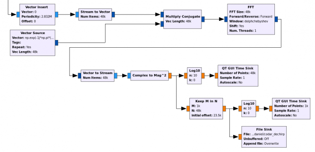
The image below shows my CODAR dechirper GNU Radio companion flowgraph (you can click on the image to view it in full size).

The samples from the Hermes-Lite come at 48ksps from the top of the image into the “Vector Insert” block. This block is used to correct the clock drift of the Hermes-Lite. First, I’ve run all the receiver without this block and judging by the slant in the images, eyeballed that the TCXO runs a bit too fast. This is compensated by inserting an extra sample (with the value zero) every 2832000 samples, using the “Vector Insert” block. If the clock ran a bit too slow, the “Keep M in N” block could be used to remove one sample periodically. I prefer to use these blocks for simplicity, rather than running an arbitrary resampler with a rate very close to 1.
The replica is generated in the Vector Source. This just uses Numpy to generate a downchirp of the appropriate characteristics. The same downchirp is repeated every 48000 samples. The downchirp uses a GUI variable to set the start (or phase) of the chirp. This is used to synchronize the replica to the received signal as I have explained above. The Vector Source generates vectors of 48000 samples to ensure that the start of the chirp gets changed in a consistent manner each time that the GUI variable is updated. Otherwise the Vector Source resets itself and you loose any synchronization between the Vector Source and the samples coming from the Hermes-Lite.
The received signal is multiplied by the replica to perform dechirping and then an FFT is done to perform spectral analysis and obtain the multipath components. The FFT length is 48000 samples, or one second, matching the chirp repetition rate. This gives a resolution of 1Hz/bin, which corresponds to a delay of 34us/bin, or a range of 10195m/bin. It is tempting to use a longer FFT to get improved range resolution. However, this is of no use. Since the received signal and the replica are not perfectly aligned in time, you get small gaps in the dechirped signal every second, when the received signal and replica do not match. This produces AM sidebands at 1Hz and multiples, which are perfectly visible when a longer FFT is used. Still, a resolution of 10km/bin is pretty good for ionospheric study.
The FFT uses the Dolph-Chebyshev window. I have already spoken about it in relation to OTH radar processing. Basically, it is good for radar applications because it minimizes the main lobe width, subject to the condition that all the sidelobes are smaller than a certain constant (and then, interestingly, all the sidelobes have the same size). Here I am using a sidelobe attenuation of 50dB, since the main signal is usually weaker than 50dB above the noise floor, so the sidelobes get buried in the noise.
After the FFT, I take the modulus squared, to get spectral power density, since I am not interested in Doppler information, which is contained the phase of the FFT. The whole spectrum is plotted using a QT Time Sink. Since I don’t want to save the full 48kHz of spectrum, I select the central 1kHz using a “Keep M in N” block and save this to a file for later processing with Python. I also display the central 1kHz with a QT Time Sink to make sure that the received signal and the replica are well synchronized.
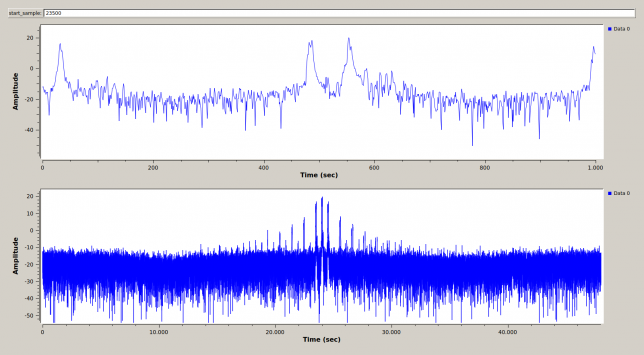
The receiver can be seen working in the figure below. The lower graph displays the full 48kHz of spectrum after dechirping (i.e., the output of the FFT). The upper graph shows only the central 1kHz of spectrum, which is what gets saved to the file.

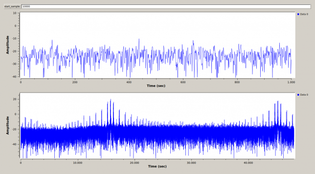
On the top of the window, there is the start_sample input field. This must be adjusted to synchronize the replica with the received signal. When they are synchronized, the dechirped signal will appear at the centre of both windows, as it happens in the figure above. If the signal and replica are not synchronized, instead we get two signals which are not centred, as the figure below shows. When the flowgraph is started, the start_sample field must be adjusted until we get a centred signal.

Note that the dechirped signal is not a single CW carrier, but rather has sidebands at 500Hz and multiples from the central carrier. The reason for this is that the transmitter gates the signal at a frequency of 500Hz in order to listen between pulses. Therefore, we get AM sidebands at the gating frequency.
Several distinct transmitters can be seen both in the figure showing the GNU Radio receiver and in the image on top of this post, where at least 3 strong transmitters, and perhaps some weak transmitters can be discerned. The multipath behaviour of these transmitters follows the same general pattern as the ionosphere changes throughout the day, but there are noticeable differences, since the transmitters are not in the same location. I still have to study how many transmitters there are and try to find their locations. I am grabbing data for several days and will discuss my findings in a future post.
The GNU Radio flowgraph used in this post can be found in this gist.
The Python code to do the plotting is really simple. The file saved in GNU Radio is memmap()ed, the spectral power density is averaged in time and plotted with Matplotlib to a PNG file. The code can be found in this Jupyter notebook.
I am averaging 45 seconds per pixel, which gives a resolution of 1920 pixels per day, perfect for viewing a whole day in HD screens. The variables a, b are used to select the frequency range to plot. These are adjusted by hand to include all the multipath components. The range resolution is 10km per pixel. I am saving each 24 hour chunk in a different PNG file. These can be stitched later with convert from ImageMagick.

Fascinating write-up; thanks for taking the time to do that.
Is it possible to assign any general description at all to the “changes in the ionosphere” that these reflections illustrate? Altitude? Distance relative to transmitter? Distance relative to receiver? Some other characteristic?
Thanks!
The vertical axis of the CODAR image represents the distance that the signal travels between the transmitter and my receiver. For a single hop propagation, picture the signal going up to the ionosphere and bouncing back down towards my receiver, as in the image below.

Thus, the distance that the signal travels depends on the height of the ionosphere layer where it bounces off. If it is higher, it will travel a longer distance and the trace will appear higher in the CODAR image. Most of the time, the signal doesn’t travel by a single path. Perhaps some of the signal bounces off a lower layer and some of it bounces of a higher layer, so you get two (or more) traces.
This is for a simple single hop. There are also multiple hops, ducting and all sorts of things.
Very interesting. I have a Hermes Lite 2 and am interested in looking into this myself. I am relatively unfamiliar with how to get GNU Radio to talk to the Hermes Lite. Any assistance would be appreciated.
Hi David, you can use either gr-hermeslite2 or gr-hpsdr.
Suppose you have a direct path from the transmitter, would that help? I’ve seen at least one of these things fairly close to my house; it’s in the parking lot of a town park near the beach. Not much to look at, just a vertical antenna on a pole connected to a medium-sized electronics box with a “Scripps Institute of Oceanography” sticker.
I think that would be helpful. On the one hand, you get the direct signal, which is always useful to do pulse compression instead of having to generate a local model. On the other hand, and probably more importantly (I’m thinking about passive radar rather than ionospheric sound, as we mentioned in Twitter), chances are that you’ll get bounces from airplanes, with a round trip time much shorter than the first ionospheric bounce. Perhaps it isn’t too difficult to detect those bounces.
Where I am, in the centre of Spain, I get these CODAR signals from +300 km away in the coast via at least one ionospheric bounce. Even if there are also bounces from airplanes, those also involve a ionospheric bounce, so it’s hard to detect whether you have an airplane.
But come think of it, I know next to nothing about how a professional OTHR works. There must be some ideas to distinguish ionospheric backscatter from backscatter on objects. The simplest idea that comes to mind is Doppler.