LEV-1 is a small lunar hopper that was carried by the SLIM lunar lander. It was released a few metres above the surface on January 19, as part of the lunar landing of SLIM. LEV-1 transmits telemetry in the 435 MHz amateur satellite band (it has an IARU satellite coordination approval), and also in S-band. Shortly after the landing, CAMRAS received the 437.410 MHz signal from LEV-1 using the 25 m radiotelescope at Dwingeloo. They have published a couple of IQ recordings in their directory of miscellaneous recordings (see the filenames starting by slim_).
The information about the telemetry signal of LEV-1 is scarce. Its website just says
Telemetry format of LEV-1 stands on CCSDS. The contents of telemetry are under developing.
The IARU coordination sheet contains other clues, such as the mention of PCM/PSK/PM, CW, and bitrates of 31, 31.25 and 32 bps, but not much else. Regardless of the mention of CCSDS, I have found that the signal from LEV-1 is quite peculiar. This post is an account of my attempt to decode the data.
In this post I will only be looking at the file slim_2024-01-19_15_39_58_437.200MHz_1.00Msps_ci16_le.chan0.sigmf-meta. I guess that the chan0 and chan1 in the filename refer to the two polarizations at the feed, but the SNR is similar and strong enough to decode in each polarization, so it is enough to look at one of them. There is another recording done 10 minutes later, but it contains signals similar to this one.
The waterfall of the moment when the LEV-1 signal first appears is plotted using Inspectrum and shown here (click on the image to view it in full size). Two things stand out. First, there is noticeable fading. This is the only significant fading in this recording, but the second recording also shows some signal strength changes. This would be difficult to explain if LEV-1 was completely stationary on the Moon’s surface, and suggests that the hopper was moving.
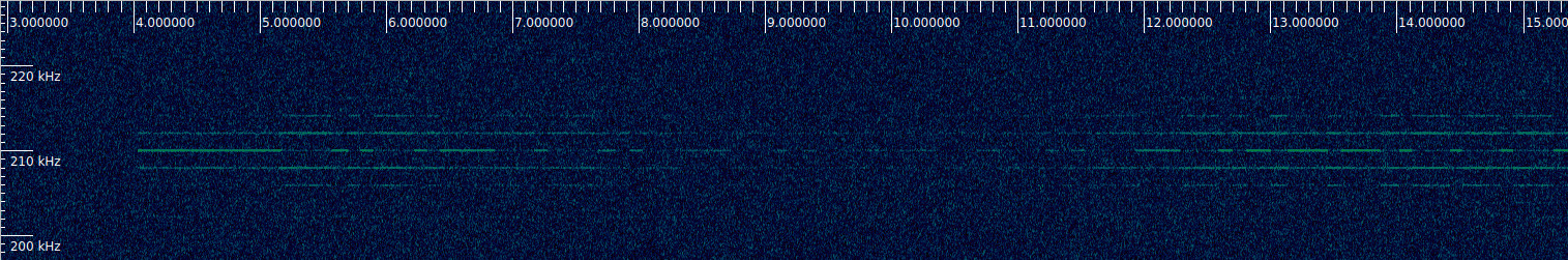
The second unusual thing is that there is amplitude shift keying in the signal. This signal is in fact a typical PCM/PSK/PM signal, but the residual carrier is amplitude shift keyed with what looks like Morse code. Modulating the residual carrier in this way is highly unusual, because the residual carrier is supposed to be a stable phase reference for the demodulation of the signal, so shift-keying its amplitude doesn’t look like a great idea. The low-level amplitude of the residual carrier (which corresponds to the gaps between the dits and dahs) is very low, and the carrier almost disappears in the waterfall.
The telemetry subcarrier has a frequency of 2048 Hz and a symbol rate of 64 baud. This frequency zoom level is too low to see the modulation, so the telemetry subcarrier appears like a CW carrier at either side of the residual carrier. Its power level changes somewhat due to the amplitude shift keying of the residual carrier, but these power changes are much smaller than those of the residual carrier. Additionally, when the residual carrier is in the low-amplitude level, the second harmonic of the telemetry subcarrier is well visible in the waterfall.
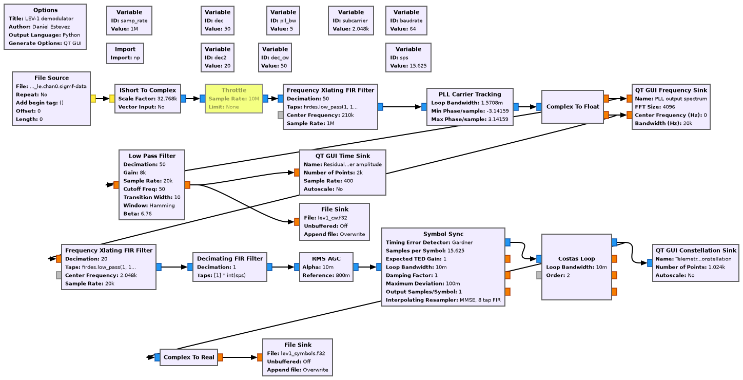
Despite the amplitude shift keying on the residual carrier, it turns out a PLL can do a good job at tracking the phase of the residual carrier. I’m using a rather narrow PLL bandwidth of 5 Hz, which is quite reasonable for a UHF signal. I am using the following GNU Radio flowgraph to demodulate the PCM/PSK/PM telemetry signal and also to extract the amplitude data from the residual carrier.
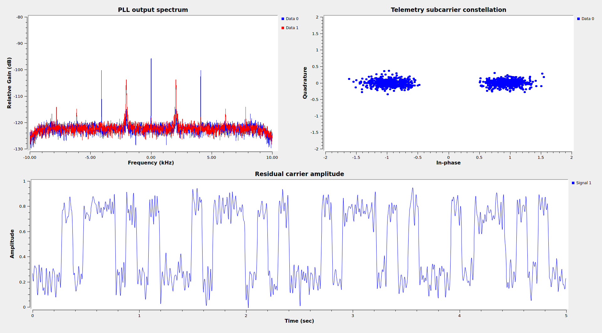
This is what the GUI of the demodulator shows when running with this recording. Since the telemetry is only 64 baud, the constellation plot with this SNR is excellent. Note the second harmonic of the telemetry subcarrier, which appears in the in-phase component. This is typical when the subcarrier zero-crossings are smooth instead of instantaneous, since the smooth zero-crossings modulate the residual carrier amplitude.
After arriving to this point, I tried to determine the CCSDS coding without success. I used my typical approach of correlating the symbols against each of the CCSDS syncwords, and also performing Viterbi decoding for each of the possible variations of the CCSDS code and then correlating against the 32-bit syncword. I also tried to look at the autocorrelation of the symbols, but this didn’t yield any patterns.
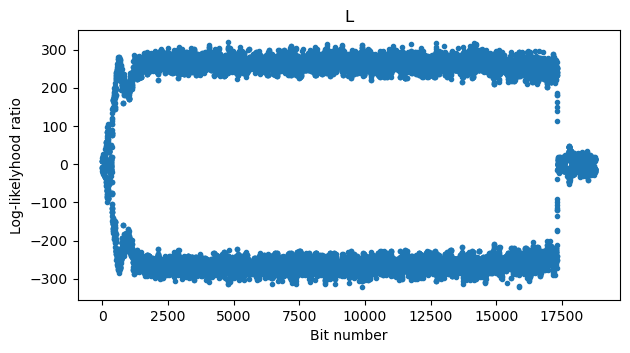
Since none of this worked but the clue of 32 bits per second mentioned in the IARU coordination sheet compared with the 64 baud symbol rate strongly suggested the presence of convolutional coding, I did some more work to check if this signal was convolutionally encoded. I used the BCJR decoder that I had done for Voyager I with each of the 4 possible variants of the CCSDS code (two possible orders for the polynomials, plus an optional bit inversion in one of the encoder branches), as well as the two possible pairings of symbols. The nice thing about a BCJR decoder in comparison to a Viterbi decoder is that its output is LLRs (log-likelihood ratios). If the decoder is set for the wrong code, the LLRs will look like a mess, but if the decoder is set for the correct code, the LLRs will form a clean “constellation” that avoids values around zero. Of all the combinations tested, the CCSDS/NASA-GSFC convention with no inversion in one of the branches gave good LLRs, as shown here.
The output of the BCJR validated that I had found the correct convolutional code, and provided the decoded stream of bits. Still, I couldn’t find any syncword in this stream, and the autocorrelation didn’t shown any patterns. Plotting the bits as a raster map with an arbitrary width gave a randomly looking image. This made me suspect that the signal was scrambled with an asynchronous scrambler, so I tried a to descramble it using a few common algorithms, and then looked at the raster map again.
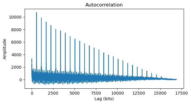
The G3RUH descrambler gave something that still looked random, but the Intelsat IESS-308 descrambler gave something that looked promising. The output had long runs of zeros (after correcting for a polarity inversion caused by the BPSK 180 degree phase ambiguity). Moreover, the autocorrelation of the descrambled bits showed very large peaks at a lag of 560 bits and its integer multiples.
Still, no trace of any of the CCSDS syncwords. I plotted the raster map of the bits using a width of 560 bits, and noticed that some of the columns of this raster map looked like what could be a syncword. Writing these columns in hex gave 0xAAAAFAF320. The 0xAAAA part is just a series of alternating ones and zeros. The kind of thing that you would use as a preamble to train a receiver clock. But the 0xFAF320 part is a commonly used syncword. I know that it is used in CCSDS Proximity-1 (I mentioned this recently in my post about the MOVE-II cubesat), but apparently it is also used in IRIG 106. A Google search for “FAF320 syncword” reveals many results. Of special interest is this NASA report, which lists all the CCSDS syncwords, as well as the HDLC 0x7e flag (which I had also tried to search in the stream of bits), and mentions the relation between 0xFAF320 and IRIG.
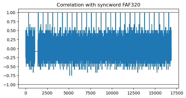
Indeed, correlating the stream of descrambled bits with the syncword 0xFAF320 reveals peaks every 560 bits. There is an exception to this, which is the first and second peak. They are at a distance of 1120 bits. I think that the explanation is that the first frame was of a different type, which was twice the length of the other frames.
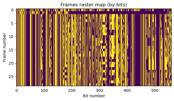
The next figure shows the raster map of the bits in each frame. The width of the raster map is 560 bits, so the first two rows should be understood as the first frame, which is twice as long. It is apparent that it has a different format compared to the other frames. Its final part is all zeros. The remaining frames have all the same format, and fields that line up are apparent.
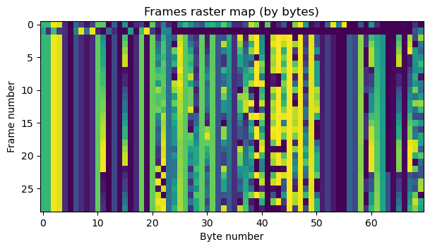
The following figure is the same kind of raster map, but with bytes instead of bits. Here it is clear that there are some telemetry fields that have increasing values. Some of these fields are 16-bit wide, because when a byte overflows, the previous byte increments by one. The last 2 bytes might be a CRC-16, but I haven’t managed to find the algorithm (there are many possible algorithms, and it is not clear if the preamble or syncword should be included in the CRC calculation).
I haven’t reverse engineered the telemetry data beyond this. It is not so easy, since there isn’t much telemetry to try to find patterns, and it doesn’t seem to follow CCSDS protocols. It would be great to have more documentation about the telemetry from the LEV-1 team, specially since this spacecraft is using the amateur satellite service and has gone through an IARU coordination process (in which one of the questions is whether technical documentation about the telemetry will be publicly available).
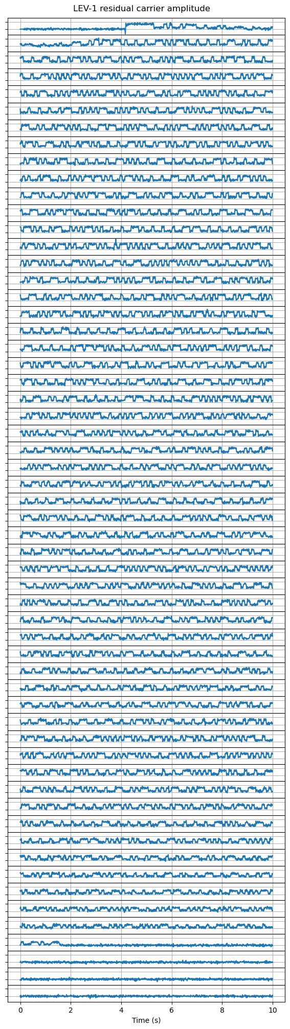
Now let us turn our attention at the Morse code modulating the residual carrier in amplitude. The next figure shows the amplitude of the residual carrier throughout all the recording. Each 10 second segment is represented as one trace in the plot. The plot should be read left to right and top to bottom as if it was text. To me it is clear that this is intended to be Morse code, as opposed to digital amplitude-shift-keying. All the runs of low levels and high levels appear to be have length 1 or 3, which is what happens in Morse. A digital ASK modulation would typically have runs of other lengths. The IARU coordination sheet also mentions “CW morse beacon contains housekeeping data”.
Despite being almost sure that this is Morse, it looks like nonsense to me. Many regular characters can be recognized, but there are also some strange sequences that might be rare prosigns (-….-.. and …-…. for instance). I have seen that other satellites transmit binary data in hexadecimal in Morse, but this doesn’t seem to be the case. Maybe some other radio amateurs can find the meaning of this, or perhaps someone from the LEV-1 team can tell us what this means.
In summary, what I have found about the LEV-1 437.41 MHz telemetry is that it is PCM/PSK/PM with a symbol rate of 64 baud and 2048 kHz subcarrier. The residual carrier is modulated in amplitude with Morse code. The telemetry signal is convolutionally encoded using the CCSDS/NASA-GSFC and no inversion in one of the encoded branches (correction: the convolutional code has inversion in one of the branches, so it is exactly as the code recommended by CCSDS; see update below). There is IESS-308 scrambling before the convolutional encoding. The frames have a 0xAAAA preamble followed by the syncword 0xFAF320. However, the contents of the frames and the meaining of the Morse code data are unknown.
The GNU Radio flowgraphs and Jupyter notebooks used in this post, as well as the intermediate data files can be found in this repository.
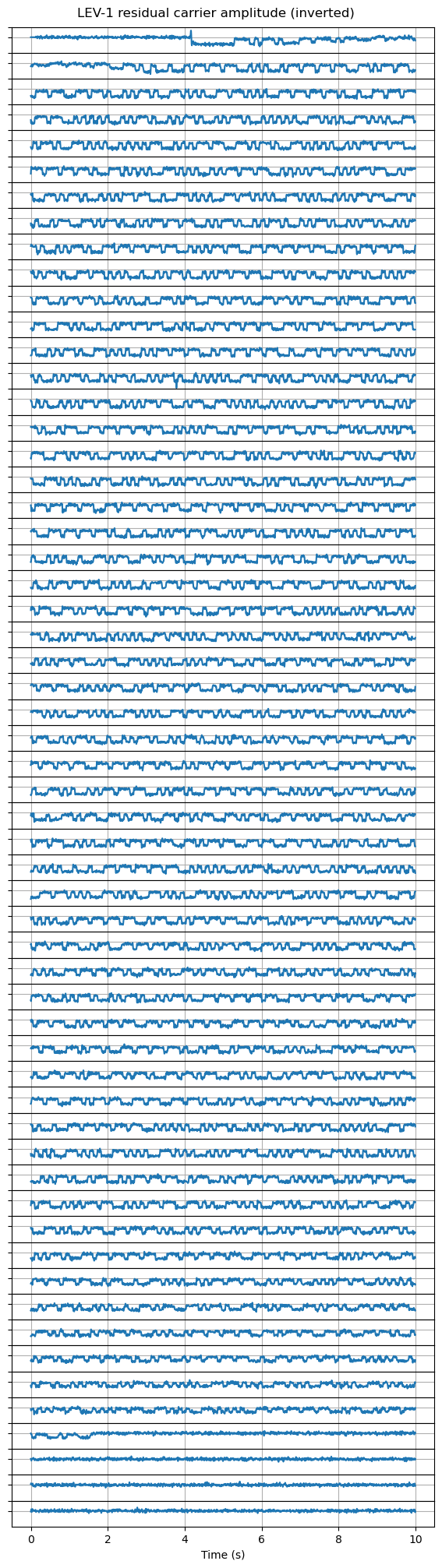
Update: Norbert DL8LAQ has figured out how to read the Morse code. It turns out that it is inverted: the dahs and dits are represented by a low amplitude on the residual carrier, and the gaps by a high amplitude. I don’t know what was the reasoning behind this, since when one listens to the residual carrier, what is heard would be the opposite of what one expects. Perhaps it was intended to listen the Morse code off the second harmonic of the telemetry subcarrier, for which the dahs and dits correspond to high amplitude levels.
Here is the same plot as above, but with the sign of the amplitude inverted. Now it is clear what Norbert says: the transmission is CQ CQ DE JS1YMG” followed but a lot of hexadecimal data. The gaps between words are the same length as the gaps between letters, but otherwise this is perfectly readable Morse.
Update 2024-01-22: Scott Chapman K4KDR has found that the last two bytes of the frames are indeed a CRC-16. The CRC algorithm is CRC-16-CCITT-FALSE (see this online calculator), but there is the catch that the data included in the CRC calculation starts 3 bytes after the 0xFAF320 syncword. The three bytes that must be skipped are 0x003e20 in all the frames. This is probably some sort of header. This only applies to the 560 bit frames. I haven’t been able to find a way to validate the CRC of the first frame in the recording, which appears to be a 1120 bit frame (and the three bytes after its syncword are 0x005632 instead). I have updated the Jupyter notebook to include the CRC check, showing that all the frames except this first longer frame have a valid CRC.
Update 2024-03-06: I have realized that the convolutional code does have inversion in one of the branches. The reason why I thought there was no inversion is because my BCJR decoder had the inversion logic incorrectly labelled: it was always doing an inversion (since it was adapted from a Voyager-1 decoder, which needs this), and then it was doing an additional inversion when inversion was enabled. I have realized this when updating the GNU Radio decoder to include a Viterbi decoder. The GNU Radio decoder flowgraph now has two Viterbi decoders (one for each possible pairing of input symbols) followed by IESS-308 descramblers, and the output of these is saved to a file.
Hi Daniel, the cw begins with “cq de js1ymg fb79e05fff5bbcb43c6296b243ac3eb7b3dac2ffffff0301f7ef2cc ….”
To read the cw code I had to turn the picture by 180° and flipped it horizontaly. After that one can read from bottom to top.
Has then been any additional signal from Lev-1 or its associates since January? De N5UTV Tulsa ok. Could it be heard on a 1 or 3 meter dish?
Hi Dave, LEV-1 was active only briefly (a few hours?) after landing. SLIM, on the other hand, has been active for several lunar days after landing, greatly exceeding expectations, but I think it isn’t active any more.
Great work – very interesting! Sorry if I’m missing something obvious, but after reviewing the flowgraph & resulting output files, I am not seeing the standard HEX frames (based on the syncword 0xFAF320) that we normally see as an output from many of these decoding projects. I see output files of BITS but at first try, I’m not able to “Sync & Create Packed PDU” to create the hex-style output that we typically use when a syncword is known. Any help with how to accomplish that last step would be much appreciated!
Hi Scott, the flowgraph only performs demodulation. I did everything else only in Jupyter. To get frames in the flowgraph you need to add a Viterbi decoder (and actually two branches of it, one operating on the symbols as such, the other operating on the symbols with a delay of one). Then an IESS-308 Descrambler block (for each branch). And only at this point you can use the Sync & Create Packed PDU with a syncword of 0xFAF320 (for each branch).
Great – thanks! I was not sure which steps were remaining. Much appreciated!
Here’s the full CW, transcribed by Dick PA2DW:
CQ CQ DE JS1YMG FB79 E05F FF5B BCB4 3C62 96B2 43AC 3EB7 B3DA C2FF FFFF 0301 F7EF 2CC3
PSE R CQ CQ DE JS1YMG FB21 E05F FF57 BBB3 3A65 9FA0 41AD 3CB9 B7DB BAFF FFFF 0002 09EE 2F6B
PSE R CQ CQ DE JS1YMG FAC0 E05F FF57 BBB3 3A63 A1A1 41AC 3CBB B8DC B3FE FFFF 0002 09ED 2F04
PSE R CQ CQ DE JS1YMG FA5E E05F FF57 BBB3 3A61 A2A2 42A9 3DBC B9DC ADFF FFFF 0002 09EC 2C9A
PSE R CQ CQ DE JS1YMG F9FF E05F FF57 BBB3 3B5F A2A2 42A3 3DBD BADD A8FF FFFF 0003 0AEB 2F35
PSE K
Great, this looks like a pattern of “CQ CQ DE JS1YMG PSE R” (R->K at the end)… The data being somewhat similar and probably telemetry, may be it is some kind of packed coordinates (what is used on the Moon as reference as lat/lon/hgt?) . A quick Perl `unpack` for 8|8|8|4 Bytes and unpacking those as 3 big-endian floats and a short shows this:
12429.8056640625 4.54512658620843e-08 44.8166542053223 14150
12428.5478515625 4.49856152329176e-08 45.8166580200195 14640
12368.796875 4.49856081274902e-08 46.0666618347168 14640
12365.3173828125 4.49856010220628e-08 46.3166618347168 14640
11857.568359375 4.52175967780022e-08 48.3166656494141 16688
Does it make sense as coordinates +α?
Earlier I checked a few known morse code tables for transmitting Japanese, it doesn’t look like text (and it is repeated).
73 DE LZ2SAF/DE
The posting ate some syntax, trying again 🙂
Great, this looks like a pattern of “CQ CQ DE JS1YMG [28B_DATA_HERE] PSE R” (R->K at the end)…
This numeric data doesn’t look like something I can immediately make sense of. So for all I know it could be anything. The interpretation as big-endian float32 seems right, though. Often when you do this with data that is in another format you get absurdly large or small floats, or NaNs.
Hi Daniel,
Nice work on the decoding so far. I haven’t tried looking at the raw data yet, but looking at the waterfall plot you made, I’m wondering if the signal isn’t FM where the modulating signal is a 2 kHz tone of varying amplitude? The regular lines on the waterfall look a bit like the beloved Bessel functions of FM. The amplitude of the modulating signal will affect the level of the carrier in the way you see if this is what is going on.
Cheers
Randall VK6WR
Hi Randall, the signal is phase modulated. This is closely related to frequency modulation. But the amplitude of the 2 kHz subcarrier doesn’t change. What changes is the amplitude of the residual carrier.
Congratulations for to all radiohams who have taken part to this new “small step for a (old-man), a giant leap for mankind”.
Hpe it will attract many young newcomeres to hamradio.
73
Jran, f6fqx
PA2DW offered a nice CW decoding (see previous comments by Tammo). Could that be Kanji?
It is hexadecimal data.
Hi,
I’ve checked the link budget https://robotics.isas.jaxa.jp/lev/LEV_HAM_Club and its seems not to be reliable.
They present -144dBm while it should be -133dBm with displayed data, I was just wondering if I made any mistake in my calculation.
I just wanted to determine the minimum antenna gain required to receive LEV-1 on 70cm.
It seems that only large antenna were able to receive its signal, does anybody have more info?
73s, Fabio IZ5XRC
I think this probe only transmitted for a few days after the landing, and it’s quite likely that it won’t be transmitting any more, since lunar night already arrived at the landing site.
Should be able to use an old C band satellite dish with correct feed and focal distance.
Excellent work Daniel!
My congraturation to JS1YMG’s wonderful work!
from ex JARL Sat Ctee chair
“CQ CQ DE JS1YMG PSE R
Estimado Daniel,
Sólo puedo decir, bien alto, bravo!
Y felicidades.
73
HC3MC ELIZABETH y HC3RE Ramiro ajustando equipo para decodificar la sonda LEV-1 DESDE LA LUNA!!. Esperamos pronto un RPT permanente en FONIA EN NUESTRA LUNA anhelo de SIEMPRE. 73
LOJA RADIO CLUB desde ECUADOR felicita a la Agencia Japonesa de exploración ESPACIAL por la Señal que recibimos desde la Luna. 73