Danuri, also known as KPLO (Korean Pathfinder Lunar Orbiter), is South Korea’s first mission to the Moon. This satellite will orbit the Moon in a 100 km altitude polar orbit. Danuri was launched on 2022-08-04 by a Falcon 9 rocket from Cape Canaveral into a ballistic lunar transfer orbit. It transmits telemetry in S-band at 2260.8 MHz. Additionally, it has a high speed downlink at at 8475 MHz for science data. The S-band downlink uses LHCP (left-handed circular polarization), which is a somewhat unusual choice, as most satellites use RHCP.
Yesterday, on 2022-08-05, the CAMRAS PI9CAM team used the 25 metre Dwingeloo radiotelescope to record the S-band downlink from Danuri. It is unclear if they used the correct polarization, but nevertheless the SNR of the signal is very good. The recordings are published in SigMF format in CAMRAS data repository. In this post I analyse the recordings and show how to decode them with GNU Radio.
The telemetry downlink uses PCM/PM/PSK modulation (residual carrier phase modulation with telemetry BPSK-modulated on a subcarrier). The symbol rate is 16384 baud, and the subcarrier frequency is 147.456 kHz. The subcarrier frequency is 9 times the symbol rate. It is common to use a subcarrier frequency that is an integer multiple of the symbol rate, because in this case the telemetry sidebands have no power at the residual carrier, so less interference is caused to the receiver’s PLL.
The telemetry frames are 220 bytes frames encoded with CCSDS concatenated coding (which consists of a outer Reed-Solomon (252, 220) code and an inner convolutional code with k=7, r=1/2). The length of a frame is then 4096 symbols. This means that at 16384 baud it takes 250 ms to send each frame.
This approach of using a baudrate which is a power of 2, together with 220 byte concatenated frames, which when FEC encoded have a length which is also a power of 2, has also been used by some Chinese missions. For instance, Tianwen-1 uses the same configuration (except that the subcarrier frequency is 4 rather than 9 times the symbol rate). Chang’e 5 used 220 byte frames with a symbol rates of 2048 baud, 4096 baud, and 512 baud in different phases of the mission. Using this choice of frame length and baudrates implies that the length of each frame is a power of two in seconds, so the frame boundaries align nicely to the second boundaries.
Besides the telemetry, in the recordings done by CAMRAS the telecommand loopback is also visible, since the probe was being tracked by the NASA DSN station in Madrid. The telecommand was sending the PLOP-2 idle sequence 010101... (see Section 7 in the TC Synchronization and Channel Coding Blue Book), and no telecommand frames were sent during the recordings. From looking at the idle sequence, we see that the telecommand uses a subcarrier frequency of 8 kHz and a symbol rate of 500 baud, which are choices that follow the CCSDS standards (see Section 2.2.4 in the Radio Frequency and Modulation Systems – Part 1: Earth Stations and Spacecraft Blue Book).
The GNU Radio decoder flowgraph for the CAMRAS recordings can be seen below. The three recordings that have been published so far use different sample rates (1 Msps, 3 Msps and 500 ksps), so the input section is slightly different depending on the recording used. All the recordings are downsampled to 500 ksps.
The decoder is quite similar to other decoders I have shown in previous posts about deep space probes. A PLL locks to the residual carrier, the phase modulation is extracted from the quadrature component, and the telemetry subcarrier is downconverted to baseband using a Frequency Xlalting FIR Filter block. Then a square pulse shape filter is done, the symbol clock is recovered, and a Costas loop is used to lock to the subcarrier. The CCSDS Concatenated Deframer from gr-satellites is used to detect the ASMs and decode the FEC. Two deframers in parallel handle the 180 degree phase ambiguity of the Costas loop.
The last section of the flowgraph downsamples the telecommand subcarrier and saves it to a file. This file can then be viewed with Inspectrum to check if there are any telecommand frames.

The GUI of the decoder while processing the first recording is shown below. We can see that the SNR is very good and that in the constellation the symbols are well separated, so there shouldn’t be any bit errors.

The telemetry frames are CCSDS AOS frames. They use the spacecraft ID 0xbb, which matches the SANA assignment. There are four virtual channels in use: 33, 34, 35, 36. Each second, four frames are transmitted using each of the four virtual channels in this order. Therefore, the four virtual channels get equal bandwidth: each can send one frame per second.
The AOS frames have a 2 byte insert zone. I don’t know what it is used for. Its contents seem to vary quite a lot. The transfer frame data field carries a single Space Packet of fixed size (212 bytes including the header). Each of the virtual channels only sends packets with one APID. The mapping between virtual channels and APIDs is straighforward: virtual channel 33 sends APID 673, virtual channel 34 sends APID 674, virtual channel 35 sends APID 675 and virtual channel 36 sends APID 676.
The Space Packets contain a time code near the beginning. The units of this time code are 1/8-th of a second, and all the four Space Packets sent in each second (with APIDs 673, 674, 675 and 676) have the same timestamp, even though they are radiated at different instants. This is normal if the values of all of the Space Packets are latched simultaneously.
I’m not completely sure of what is the length of the time code, because I don’t know if some bytes should form part of the MSBs of the time code or not. The most reasonable choice I’ve found is a 24-bit time code composed of bytes 3, 4 and 5 (starting to count by 0) in the packet user data field. With this choice, the epoch for the code could be 2022-07-30T12:00:00 UTC, since there is an error of a fraction of a second between the time codes with this choice of epoch and the timestamps of the CAMRAS recordings. This could make sense, since such an epoch is a few days before launch, and 12:00 is the start of Julian days. If we try to make the time code wider by taking some of the previous bytes as MSBs, then the epochs we get do not make much sense (in the sense that they are not nice round numbers). Such a 24-bit time code would roll over every 24.3 days, so we will be able to see if I’m right if we receive more data later on in the mission.
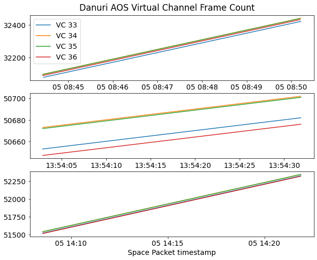
The figure below shows the evolution of the virtual channel frame count field in the AOS primary header for each of the recordings. The sequence count field in the Space Packet primary header contains the same value as the 14 LSBs of the virtual channel frame count of the corresponding AOS frame (the Space Packet sequence count is only 14 bits wide). Interestingly, the virtual channel frame counts for the four virtual channels are close, but they are not equal.
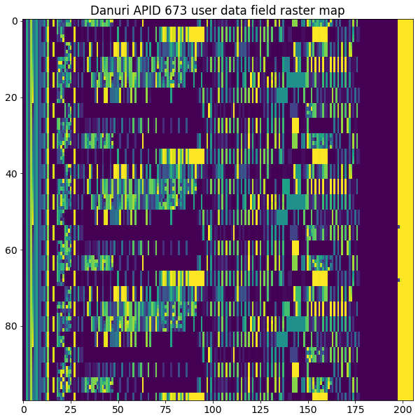
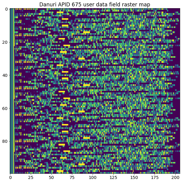
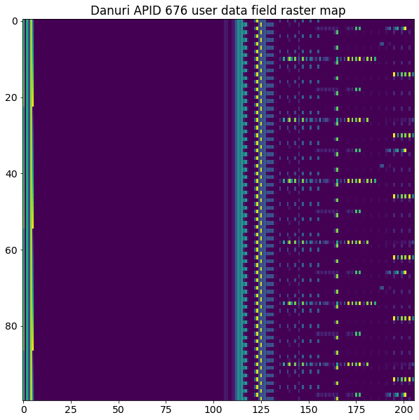
Below we show raster maps for the user data field of the Space Packets of each APID. Each packet is represented as one row, with one byte per column. The colour coding corresponds to the values of the bytes. Only the first 100 packets of each APID are shown. This is enough to get an idea of how the data looks like. There are some apparent structures, but most of them involve several consecutive packets, so making some sense of the data will not be easy. In particular, APID 675 seems the busiest or more random.
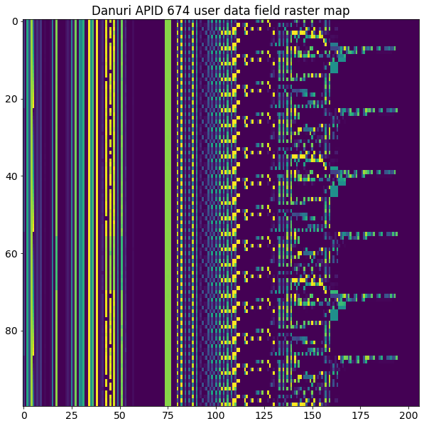
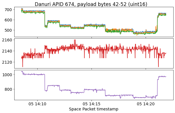
I have been able to spot some bytes near the beginning of APID 674 that when plotted as uint16 values seem to make some sense as telemetry variables. I don’t know what they represent. Perhaps the sudden jumps they show could give a clue.
Code and data
The materials for this post are contained in this repository. The frames have been analysed and plotted in this Jupyter notebook. The GNU Radio decoder is kplo_decoder.grc. The decoded frames are contained in .u8 files. The IQ recordings can be found in the CAMRAS archive.
A very interesting holiday read, thanks!
Hi Daniel,
I am Pallavi ,working on a Satellite demodulation project.
I need some clarification regarding the GRC flowgraph,
1) Why is the quadrature component after PLL being selected for further downconversion rather than the In-phase component?
2) How did you get to know the subcarrier frequency is 147.456KHz?
3) Is 6e the frame sync word? Is it being fed to the GRC? How did you get to know about the frame size?
Thanks and Regards
Hello Pallavi, you can find answers to your questions in my ‘Decoding interplanetary spacecraft’ workshop. The sync word is not 6e, though. I don’t know where you got that impression. It’s the usual 0x1acffc1d used for concatenated data.
Thank you very much Daniel. Will look through.
Hi Daniel, could you please tell me how did you calculate the down-sampling frequency to be 500Ksps?
The recording sample rate is 1 Msps and I’m decimating by 2.
I would like to know why the sample rate is decimated before further processing.
Is 500ksps a fixed value or can it be changed?
500ksps is an appropriate value for this kind of signal, but it can be changed. It’s not the only value that will work.