Last weekend, AMSAT-DL started some test transmissions of a high-speed multimedia beacon through the QO-100 NB transponder. The beacon uses the high-speed modem by Kurt Moraw DJ0ABR. It is called “high-speed” because the idea is to fit several kbps of data within the typical 2.7 kHz bandwidth of an SSB channel. The modem waveform is 2.4 kbaud 8APSK with Reed-Solomon (255, 223) frames. The net data rate (taking into account FEC and syncword overhead) is about 6.2 kbps.
I had never worked with this modem before, even though it served me as motivation for my 32APSK modem (still a work in progress). With a 24/7 continuous transmission on QO-100, now it was the perfect time to play with the modem, so I quickly put something together in GNU Radio. In this post I explain how my prototype decoder works and what remains to be improved.
In this post I continue with the analysis of an LTE downlink recording, which I started by looking at the primary and secondary synchronization signals. This recording is a one second excerpt of a 10 MHz cell in the B20 band that I recorded close to the base station, with a line-of-sight channel.
Now we will handle the reference signals to perform channel estimation. This will be used to equalize the received data transmissions. We will also handle the transmit diversity used by the base station, and show how to locate and demodulate some of the physical channels. All the calculations and plots are done in a Jupyter notebook.
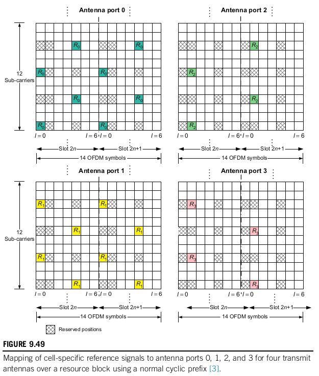
The cell-specific reference signals (CRS) are transmitted in every subframe across all the cell bandwidth. They can be transmitted on either one, two or four antenna ports. In LTE, the concept of an antenna port does not necessarily correspond to a physical antenna. Signals are said to use the same antenna port if they have the same propagation channel to the user. Therefore, different beamforming combinations of the same physical antennas constitute different antenna ports.
The figure below shows the resource elements that are used for the reference signals in each of the ports. The resource elements allocated to reference signals for the antenna ports that are active are only used for this purpose, and only one of the ports transmits the reference signal in each of these resource elements. For instance, say that the cell uses two antenna ports. Then the elements marked as \(R_0\) and \(R_1\) below will only be used for the CRS, while the elements marked as \(R_2\) and \(R_3\) are free and can be used for other purposes.
To the pattern shown above, a frequency offset that consists of the PCI (physical cell ID) modulo 6 subcarriers is applied. This is done so that the reference signals of cells having different PCIs use different subcarriers, so as to prevent interference (especially those cells in the same group, since their PCI modulo 3 is different).
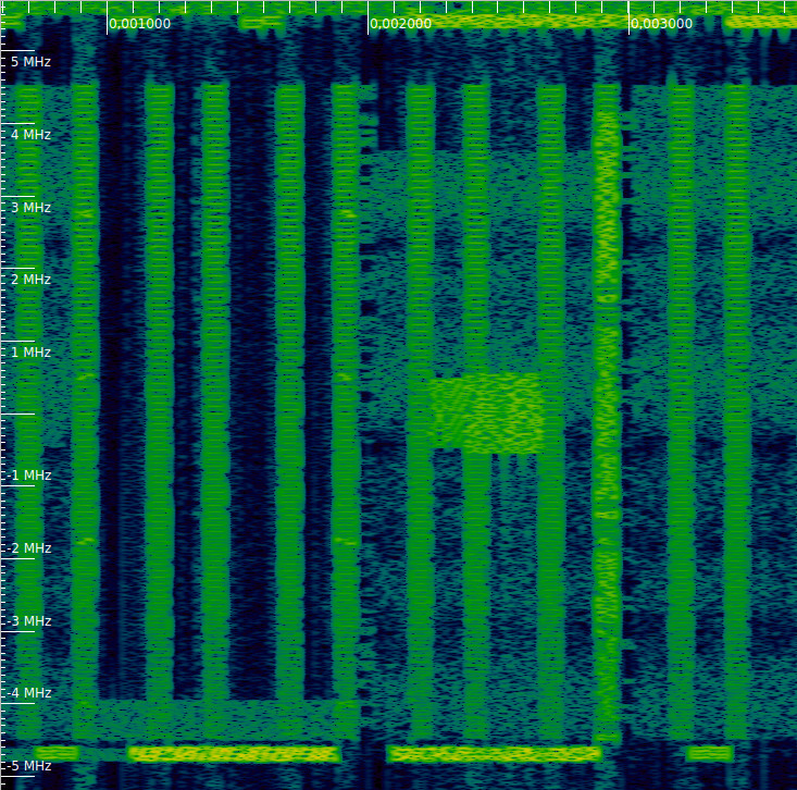
In the waterfall of our recording, we can clearly see the CRS transmissions. They last one symbol and occupy the whole bandwidth of the cell. We can also see the PSS, SSS and PBCH, as we remarked in the previous post. These indicate us where the subframes start. Thus, we can see that the first and fifth symbol of each slot are used for transmission of the CRS. This means that the cell does not use four antenna ports, since their corresponding CRS would be transmitted on the second symbol of each slot.
Waterfall of the downlink recording, showing CRS, PSS, SSS and PBCH